Why an APFC Controller Shows the Wrong Power Factor
أن APFC controller showing the wrong power factor can result from CT polarity, an incorrect voltage-phase relationship, an unsuitable measurement location, configuration errors or comparison of different power-factor definitions. First confirm that the controller and reference instrument measure the same circuit at the same time. Then verify the physical measurement scheme against the exact manual. Do not reverse CT wires or alter settings experimentally in a running panel. A negative, leading or unexpectedly low reading is a symptom to diagnose, not automatic proof that the controller is defective.
This guide separates measurement problems from genuine compensation problems. It complements automatic power-factor-controller settings and does not provide a generic connection diagram for every controller model.
Make sure the readings are actually comparable
A controller on the main incomer and an analyzer on a motor feeder do not measure the same load. Even at the same point, measurements taken at different production states may differ. Stage transitions, motor starts, generator operation and solar export can change the measured quantities quickly.
Record the instrument locations, timestamps, connected stages and load state. Identify whether each device reports total power factor or a fundamental-frequency displacement value. The displayed words may be similar while the measurement definitions differ. A nonlinear load can have good displacement power factor and a lower total power factor because of current distortion.
ال OpenStax AC-power chapter explains the sinusoidal phase relationship behind basic power factor. Distorted waveforms require the corresponding measurement definitions. Do not conclude that one instrument is wrong merely because its total-PF reading differs from another device’s cos φ display.
Identify the sign convention before interpreting a negative value
Manufacturers may use signs, quadrants or separate indicators to distinguish inductive, capacitive, import and export conditions. The meaning of a minus sign must come from the controller manual. It should not be assumed to mean the same thing as a utility meter’s import/export sign or an analyzer’s reactive-power convention.
A reversed CT or mismatched voltage phase can create an unexpected reading, but genuine reverse power or capacitive operation can also occur. If the plant has solar generation, multiple supplies or light-load overcompensation, investigate those operating conditions rather than treating every unfamiliar sign as a wiring fault.
اقرأ negative power-factor meaning for the wider interpretation. Keep the original display and the signed active/reactive readings from a suitable reference instrument so the diagnosis can distinguish physical operation from a measurement-scheme error.
Use a symptom-based diagnosis table
| عرض | Possible explanation | Evidence to obtain |
|---|---|---|
| Unexpected leading indication with stages off | Sign convention, CT polarity or voltage-phase mismatch | Manual definition, wiring scheme and reference power quantities |
| Current display differs by a nearly constant factor | CT ratio convention or wrong connected tap | Physical CT ratings, menu values and equivalent current measurement |
| Reading changes when another feeder is operated | CT measures a broader or different circuit than expected | Single-line diagram and location of the regulation point |
| Good cos φ but low analyzer total PF | Current distortion or different measurement definitions | Fundamental and total quantities plus harmonic spectrum |
| Controller adds stages without seeing improvement | CT may not include the correction response, or stage output is absent | CT/bank topology and measured branch response |
| Value is unstable at very low load | Small measurement signal or rapidly changing demand | Load level, CT range and instrument capability |
| PF is truly leading with many stages connected | Excess compensation or unsuitable minimum stage | Stage state, reactive demand and control logic |
Each explanation is a candidate. Confirm it before changing wiring or replacing equipment. Multiple errors can coexist, so fixing one scaling problem does not prove the entire measurement chain is correct.
Verify CT orientation and secondary identification
Use the approved drawing and physical identification to check CT primary orientation and secondary terminal assignments. Do not rely on wire color alone or a diagram for a visually similar device. The actual controller may use a specific phase relationship and have model-dependent detection features.
Physical inspection and correction must follow the site’s qualified-person procedure. An energized CT secondary must not be left open. The California CT-secondary rule provides a safety reference. Do not remove a conductor to “try the other polarity” while current is flowing in the primary circuit.
If the controller supports automatic phase recognition, verify its prerequisites. Insufficient load or an incorrect connection can prevent valid recognition. Repeating the routine does not substitute for checking the wiring. Save any detection result and compare it with the documented scheme before accepting automatic operation.
Check the voltage phase and connection arrangement
Power-factor calculation depends on the relationship between measured voltage and current. A correctly oriented CT used with the wrong voltage phase can produce a misleading phase angle. Determine whether the controller expects phase-to-neutral, phase-to-phase or another supported connection and which CT phase corresponds to it.
Do not assume a controller supplied from one pair of phases necessarily measures power using that same arrangement. Auxiliary supply and measurement inputs may have distinct functions. Read terminal designations in the exact manual and the panel drawing rather than inferring from the front display.
A replacement controller may have different input requirements even if it fits the same cutout. Verify the supported scheme before reconnecting the old wires. Commission the measurement relationship again instead of transferring settings and assuming the physical circuit remains valid.
Check ratio and input settings without using them as a universal fix
The CT’s primary and secondary ratings must match the controller configuration and input capability. A menu may expect primary amperes, a mathematical ratio or separate ratings. Record the convention before correcting the value. A physical 800/5 A CT has a 160:1 mathematical ratio, but the menu may require 800 in a primary-rating field.
A ratio error can affect displayed current, calculated demand and stage-response detection. It does not necessarily explain the displayed phase angle or sign. If the power factor is implausible but current scaling is accurate, continue investigating polarity, phase and measurement location.
Follow APFC CT-ratio setup for the evidence needed. Avoid adjusting the C/K value to compensate for a ratio error; correct the measurement configuration first, then review sensitivity according to the manufacturer’s method.
Confirm the controller sees the capacitor bank’s response
The regulation CT must measure the circuit the controller is intended to control. If the bank connection lies outside that measured path, connecting stages may not produce the expected change in measured reactive current. The controller can then continue adding stages or report a condition that appears inconsistent with the supply analyzer.
Review the single-line diagram for incomers, bus couplers, alternate sources and capacitor-bank connections. A topology change can alter what a CT measures. A controller arrangement that works with one transformer and an open coupler may need additional design consideration when supplies operate differently.
Use an approved commissioning sequence to observe the effect of individual stage commands. Verify that the stage actually delivers output as well as whether the controller detects it. A failed fuse, contactor, capacitor or branch connection can mimic a measurement-location problem, so both sides of the loop need evidence.
Separate real overcompensation from a display error
A leading indication can be physically correct when the connected capacitor output exceeds the load’s reactive requirement. This is common to investigate during light load, overnight operation or a production shutdown. Confirm stage status and reactive power with a suitable instrument before changing the measurement wiring.
The controller may be limited by the smallest available stage, a disabled stage or a sequence that does not match installed sizes. Target and timing settings can also affect the result. Review APFC step selection and the actual available combinations rather than assuming more total kvar is needed.
Do not force unity power factor as a diagnostic shortcut. The appropriate target must suit the plant and utility requirements, and rapid load changes can create temporary leading conditions. A stable, correctly measured suitable operating band is more meaningful than one attractive instantaneous number.
Check harmonic conditions when correction seems ineffective
Capacitor stages address fundamental reactive demand; they do not automatically remove current distortion. If the controller displays a displacement quantity while the reference instrument reports total PF, the bank may improve the former without fully improving the latter. This is a measurement-definition distinction, not necessarily a failed controller.
Obtain the harmonic spectrum and the definitions used by the instruments. Investigate whether the stage current and voltage are within the designed duty, especially if additional stages increase distortion or protective events. Equipment selection should follow the measured problem, not the assumption that a lower PF always requires more capacitors.
ال electricity authority’s APFC specification illustrates the need to consider controller protection and harmonics with setup. Confirm the actual model’s features; a generic specification does not establish that every installed device measures or protects identically.
Change one verified cause at a time
Save the original configuration, readings and stage state. Form a specific hypothesis from the evidence, make the authorized correction under the required safe conditions, and repeat the same comparison. Changing polarity, ratio, target and sensitivity together may create a plausible display without revealing which original fault existed.
After a correction, verify light-load and representative production behavior. Confirm that stage commands produce the expected measured response and that no inappropriate leading condition or excessive switching remains. Record which quantities were verified and which operating states were not available during testing.
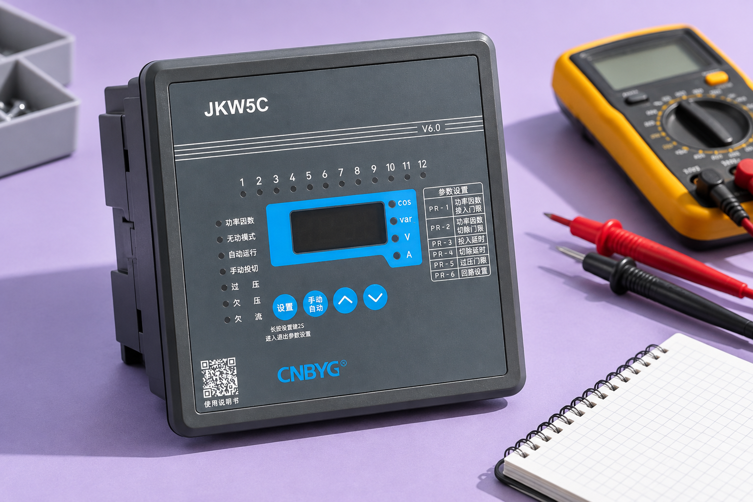
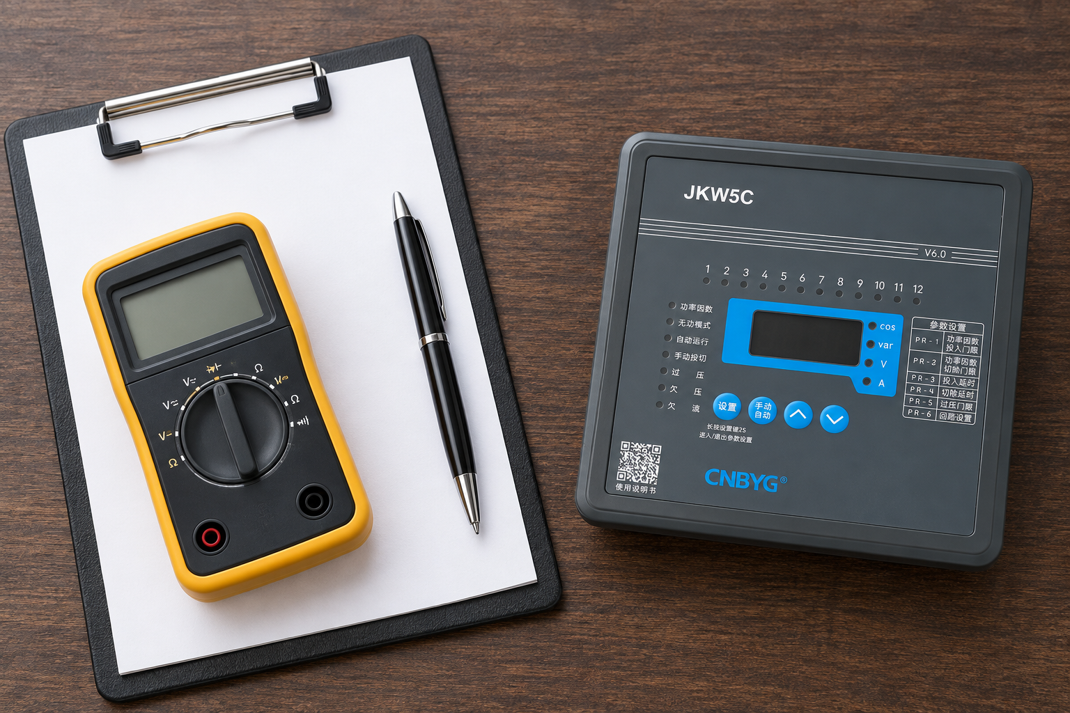
For CNBYG JKW controllers, provide the model, CT nameplate, wiring diagram, measurement location, signed reference readings and stage-operation history when requesting assistance. These facts support diagnosis more effectively than a photograph of a single PF number.
Further learning
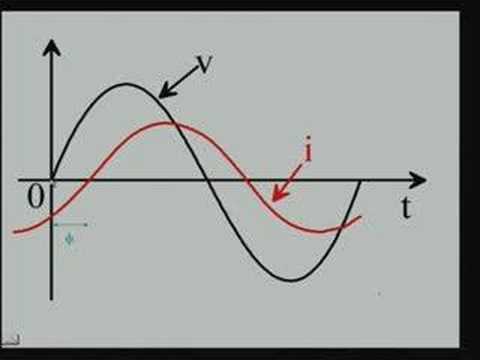
Watch Lecture – 15 Power Factor by nptelhrd
The NPTEL power-factor lecture explains the electrical quantities behind the display. Apply the exact device manual to connections, signs and configuration.
أسئلة متكررة
Does a negative reading prove the CT is reversed?
No. Sign conventions, voltage-phase relationship and real import/export or capacitive conditions can all matter. Verify the manual and reference power quantities before diagnosing polarity.
Why does my analyzer show a lower PF than the controller?
The devices may measure different circuits, operating times or power-factor definitions. Compare equivalent quantities at the same regulation point, including total and displacement PF where relevant.
Can changing the CT ratio fix an incorrect sign?
A ratio change addresses scaling under the controller’s convention. It does not correct an incorrect phase relationship or physical polarity. Diagnose those issues separately.
What should be checked after a correction?
Verify equivalent independent readings, actual stage output, the controller’s response and light-load behavior. Preserve the final wiring and settings together with the operating conditions used for the test.