How CT Ratio Errors Affect Active Harmonic Filters
How CT Ratio Errors Affect Active Harmonic Filters
An active harmonic filter (AHF) can only compensate the current it measures correctly. If its current-transformer (CT) ratio is entered incorrectly, the controller may interpret the primary current at the wrong magnitude. The resulting compensation request can be too small, too large or limited by the AHF’s output capacity. A ratio error is not the same as reversed CT polarity, a misplaced CT, a wrong phase assignment or CT saturation; each can produce a different symptom and requires a different check. Before changing harmonic settings or buying a larger filter, compare the CT nameplate, wiring, controller configuration and an independent current measurement under a known load state.
This is a diagnostic framework, not a wiring instruction for an energized panel. CT secondary circuits and AHF controls must be handled according to the installed equipment manual and an approved safe-work procedure by qualified personnel. In particular, do not disconnect a conventional energized CT secondary as a troubleshooting shortcut.
What the CT ratio actually tells the AHF
A CT converts a larger primary current into a smaller secondary signal for measurement. A nameplate such as 1000:5 describes a nominal ratio: 1000 A primary corresponds to 5 A secondary under its specified conditions. The controller must know the installed CT and signal-input arrangement to scale that secondary measurement back to an estimate of the primary current. Some systems use 1 A, 5 A or low-power sensor inputs; these are not interchangeable without confirming the exact hardware and manual.
ال IEEE C57.13 standard addresses instrument-transformer characteristics, ratio, phase-angle and polarity tests, among other requirements. IEC 61869-2 addresses inductive current transformers used with measurement or protection equipment. These standards describe transformer properties; neither provides a universal AHF menu value. The installed CT nameplate and AHF documentation remain the operational authority for the configured ratio.
An error in the entered ratio creates a scale error. Suppose a 1000:5 CT carries an illustrative 400 A primary current. Its idealized secondary would be 2 A. If a controller that expects this 5 A input is mistakenly configured as though the CT were 500:5, it would infer about 200 A, not 400 A, before considering real-world CT error and the AHF’s proprietary control behavior. The arithmetic explains the direction of the error; it does not predict the exact harmonic current an actual product will inject. Real sensors, burden, saturation, filtering and controller limits matter.
Separate ratio from placement, polarity and phase
These four errors are often grouped under “CT problem,” but confusing them delays the fix. A ratio mismatch changes the interpreted magnitude. Reversed polarity changes the signal’s directional reference. A CT on the wrong conductor or side of the compensation point measures a different current from the one the controller is designed to use. A phase assignment error pairs the wrong current and voltage channels or mixes phases in a three-phase algorithm. More than one fault may coexist.
ال AHF installation checklist addresses physical placement and pre-energization checks. This article narrows the question to detecting and verifying a CT ratio mismatch after the diagram, sensor locations and safe-work procedure are available. If the filter has been recently moved or a feeder was rebuilt, compare the as-built single-line diagram with actual CT positions before changing ratio values.

Image: an illustrative isolated-sensor inspection; it is not a wiring diagram or permission to open an energized CT circuit.
Use the symptom to choose the next check
The table is a field triage guide. Symptoms overlap, so treat every row as a hypothesis to test rather than a diagnosis from one dashboard value.
| Observed symptom | Possible CT-related cause | Evidence to collect before adjustment |
|---|---|---|
| AHF display current is consistently about a fixed proportion of an independent meter’s reading | Configured CT ratio or input type does not match the installed sensor | CT nameplate, tap used, manual input type, simultaneous primary-current readings |
| Current indication changes sign or compensation appears to reinforce the disturbance | Polarity, CT direction or control-location configuration may be wrong | Approved wiring diagram, phase references, controller polarity indication, qualified test record |
| One phase differs strongly from the others under a balanced known load | Wrong phase, unequal CT ratios or one sensor circuit fault | Per-phase CT identity, wiring trace and independent phase-current measurements |
| Readings agree at moderate load but diverge at high current | CT saturation, burden or capacity issue rather than a simple fixed ratio error | CT class, burden, current waveform and load-dependent comparison |
| AHF looks healthy locally but upstream harmonics remain high | CT placement or compensating-current capacity may be wrong | One-line diagram, feeder and PCC spectra, AHF output current and limit status |
If a supposed ratio error is not approximately consistent across repeated conditions, do not “correct” it by entering a convenient ratio. A load-dependent error may indicate CT saturation or a measurement-bandwidth issue. Harmonic current is not a perfect sinusoid, so the sensor’s suitability for the relevant harmonic content and its connection to the controller matter.
A safe, repeatable ratio verification sequence
First identify the installed CT on each phase, including model, nameplate ratio, any selectable tap and physical position. Compare that information with approved drawings and the AHF configuration. Note whether the controller expects a ratio entered as primary-to-secondary values or as a multiplier; entering the same numbers in the wrong convention can produce a severe scale error. The manual for the exact model resolves the convention.
Second, collect simultaneous independent primary-current readings at a stable operating state. The independent instrument must be suited to the waveform and positioned at the same electrical boundary as the CT being checked. Record each phase’s RMS current and, where available, harmonic spectrum. Compare the AHF’s displayed measured current—not its output-current command—with the independent reading. A good comparison uses several load levels and notes which nonlinear loads are running. Do not infer ratio correctness from a single low-current point.
Third, check polarity and phase assignment separately if a simple scale correction cannot explain the readings. Do not reverse leads on a live CT to “see what happens.” A qualified team can perform an approved polarity and wiring verification under the site’s isolation and test procedures. In the United States, OSHA 29 CFR 1910.333 addresses electrical safe-work practices; local rules and site procedures may impose additional requirements.
Fourth, document any approved configuration correction with before/after screenshots or exports, the CT nameplate and drawing revision, date, author and independent measurement results. Then repeat comparable harmonic measurements. A corrected ratio should improve the credibility of the sensed-current values, but it does not by itself prove the AHF is properly sized or that site harmonic limits are met.
Why CT ratio alone cannot explain every poor result
An AHF’s performance depends on available output current, its supported harmonic orders, control mode, CT location and the wider power system. If the output current is already at its limit during peak production, a correct CT ratio cannot create missing capacity. If the CT is upstream of other nonlinear feeders, it may sense a different total than expected. If a capacitor bank switches or source impedance changes, the upstream spectrum can change independently of the AHF.
ال AHF sizing guide for VFD loads addresses capacity selection. The harmonic compensation priorities guide addresses allocation after measurement is credible. The working-principle guide explains the current-sensing and injection sequence. These questions should be investigated in order: verify the sensed signal, confirm the filter can supply the required current, then adjust the compensating strategy.
At the utility interface, an AHF screen is not the final word. IEEE 519-2022 frames harmonic-control design goals at the point of common coupling (PCC). If a project has a PCC target, measure there with an appropriate method and the actual site loading. A correctly configured CT on a single feeder is a prerequisite for reliable local control, not a compliance certificate for the entire installation.
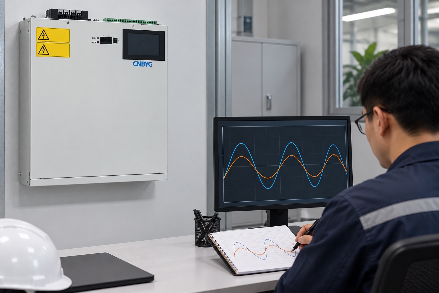
Image: illustrative waveform review near the product-referenced AHF; the traces are not measured project data.
How to discuss CT requirements in an AHF purchase request
When asking for an AHF from CNBYG, send the supplier the system voltage, wiring arrangement, one-line diagram, AHF location, CT installation point, maximum and normal feeder current, available sensor ratio and input type, and representative harmonic measurements. Ask which CT models, ratio ranges, burden limits and installation positions are supported by the specific proposed unit. Do not assume a current transformer shown in a generic photograph is included or suitable for every installation.
Require commissioning documentation to state the configured ratio for each phase, sensor polarity and location, independent current cross-checks and the final harmonic measurements. This makes future maintenance much easier: if a CT is replaced or a panel is expanded, the team can compare the new installation with an accepted baseline rather than relying on memory.
Neutral teaching video on transformer measurement error
NPTEL IIT Kharagpur’s lecture Errors in Instrument Transformer explains why instrument-transformer readings differ from ideal scaling. It is background education about measurement error, not an AHF installation tutorial.

أسئلة متكررة
Can I fix poor harmonic performance by changing only the CT ratio?
Only if a documented ratio mismatch is truly the cause. Check the installed CT, configured input, phase and polarity first; then verify current readings with an independent instrument. Capacity, placement and load changes may still limit the result.
Does a reversed CT have the same effect as a wrong ratio?
No. A wrong ratio generally mis-scales magnitude, while reversed polarity changes directional reference. Depending on control design, each can cause different indications and behavior. Diagnose them separately under the approved procedure.
Why do current readings agree at low load but not at peak load?
A fixed ratio mismatch alone usually produces a relatively consistent scale error. Divergence only at high load points toward possible saturation, burden, sensor bandwidth, instrument method or other load-dependent effects. Have the qualified team review the CT specification and recorded waveforms.
Is the CT nameplate ratio enough to enter the AHF setting?
Not always. Confirm the actual tap, secondary or low-power output type, phase assignment and the controller’s required entry convention. The exact equipment manual and as-built drawings take priority over a generic example.
Keep the corrected measurement auditable
Archive a dated package containing CT photos and nameplates, one-line drawing revision, phase and polarity test records, old and new controller settings, instrument details, per-phase comparisons at multiple load states and before/after harmonic spectra. The value of this work is not merely a cleaner dashboard number. It is a trustworthy signal on which later sizing, priority and PCC decisions can rest.