APFC Controller C/K Value Calculation
أن APFC controller C/K value is a switching-sensitivity setting associated with the smallest capacitor stage and the measurement CT ratio. Its exact definition is controller-specific. A common calculation begins with the smallest stage’s reactive current divided by the CT transformation ratio; some controllers apply an additional response coefficient, use different units or learn stage output automatically. Therefore, calculate the physical secondary-current equivalent first, then apply the installed controller’s documented convention. Copying a C/K number from another bank can cause insensitive control or unnecessary stage switching.
This guide explains the calculation inputs and a worked example. It does not prescribe one setting for every JKW or APFC controller. Begin with automatic power-factor-controller settings and confirm the exact manual before changing an operating bank.
What C/K is intended to achieve
A controller must decide whether the measured reactive error is large enough to justify connecting or disconnecting a stage. If it reacts to every tiny change, it can create excessive switching. If it ignores a meaningful error, the bank may remain short of the intended correction. The sensitivity or response band helps manage that tradeoff.
The smallest effective stage is relevant because it establishes the minimum available correction increment. The CT transformation ratio is relevant because the controller receives a secondary measurement corresponding to the primary circuit. The name C/K is historically associated with this relationship, but the menu’s actual calculation and units must be verified for the model.
Do not confuse C/K with the target power factor. The target defines the desired operating condition; the response setting influences how the controller acts around it. Likewise, a delay setting affects timing rather than the size of the reactive error needed for a stage decision. Each setting has a separate purpose.
Identify the actual smallest stage output
Use the stage’s net reactive output at the operating voltage and configuration required by the controller’s method. Do not automatically use a capacitor can’s rated kvar if the assembled stage contains several units or a series reactor. The stage drawing and approved assembly data should establish the relevant quantity.
A bank with one 10 kvar stage and several 20 kvar stages has a different minimum increment from a bank containing only 20 kvar stages. If the small stage is disabled or has deteriorated, the available correction resolution changes. Review whether the controller’s algorithm and settings account for the actual available stages.
Voltage matters because capacitor output varies with voltage in the ideal fundamental-frequency model. For detuned stages, use the manufacturer’s complete branch data rather than a capacitor-only assumption. A correct calculation based on the wrong stage quantity still leads to the wrong response setting.
Calculate primary and secondary stage current
For a balanced three-phase reactive stage, the ideal fundamental reactive current is Ic = Qstep/(√3 × U), where Qstep is in var and U is line-to-line voltage in volts. If Qstep is given in kvar, multiply by 1,000 before using this expression. The result is amperes at the primary circuit.
Define the CT transformation ratio K = Ip,rated/Is,rated. The ideal secondary-current equivalent of the stage is Ic/K. This is a physical scaling relationship. It should not be labelled the final menu C/K value until the manual’s convention is applied. Controllers may include a response coefficient or express the setting differently.
For an illustrative 10 kvar stage on a 400 V balanced system, Ic is approximately 14.43 A. With an 800/5 A CT, K is 160 and the secondary-current equivalent is approximately 0.0902 A. If a particular manual explicitly defines its response value as 0.65 times that equivalent, the arithmetic result would be about 0.0586 A. The coefficient is an example, not a recommendation for the installed controller.
Keep the example’s assumptions visible
| Input or result | Illustrative value | Condition or limitation |
|---|---|---|
| Smallest stage net output | 10 kvar | Must represent the complete stage at operating voltage |
| Line-to-line voltage | 400 V | Balanced three-phase fundamental-frequency example |
| Primary stage reactive current | 14.43 A | Derived from Q/(√3U), excluding harmonic current |
| CT ratings | 800/5 A | Physical CT and controller input must be compatible |
| Mathematical CT ratio | 160 | Primary rating divided by secondary rating |
| Secondary-current equivalent | 0.0902 A | Physical scaling result before menu convention |
| Example response coefficient | 0.65 | Apply only if explicitly required by the actual manual |
| Example coefficient-adjusted value | 0.0586 A | Not a universal C/K setting |
The calculation demonstrates unit handling and convention differences. The electricity authority APFC specification includes automatic and manual C/K setup requirements, showing why the chosen controller’s implementation matters. It does not make one response coefficient appropriate for every device.
Check CT setup before judging C/K
A physical 800/5 A CT does not guarantee the controller is configured for K = 160. The menu may ask for primary amperes, a mathematical ratio or separate primary and secondary values. Confirm what was entered and whether the connected secondary tap matches the documented rating.
If scaling is wrong, recalculating C/K using the assumed CT ratio can conceal rather than solve the measurement error. Check controller input compatibility, polarity, voltage-phase relationship and CT position as separate items. The bank must be measured at the regulation point where stage response can be seen.
استخدم APFC CT-ratio setup to document those inputs. Physical CT work requires qualified personnel and the approved procedure; an energized secondary must not be opened. The California CT safety rule provides a reference for that hazard.
Understand symptoms of a response band that is too narrow
A narrow response band can make the controller react to small load changes or measurement fluctuations. It may connect and disconnect stages frequently, especially where the smallest stage is too large for the light-load demand. The visible symptom can be repeated switching between lagging and leading conditions.
However, frequent switching is not proof that C/K alone is wrong. The target, stage sizes, timing, CT arrangement, unstable demand and stage-capacity deterioration can all contribute. Review a time-aligned log of reactive demand, power factor and stage operation before changing the threshold.
Do not widen the band merely to hide a wiring or stage fault. A stable display after disabling effective control is not a successful correction. Identify which physical limitation or configuration error produces the behavior, then make one documented change at a time.
Understand symptoms of a response band that is too wide
A wide response band can leave a reactive error that is large enough to matter operationally but too small to trigger the controller’s configured action. The bank may appear slow or fail to use available stages near the target. This can be mistaken for insufficient total kvar.
Compare the smallest usable stage with the remaining reactive demand and the manual’s decision rules. At light load, the controller may correctly avoid a stage that would create overcompensation. Do not interpret every unconnected stage as a failure. The relevant question is whether the bank can achieve a suitable available state within its intended control logic.
If no valid combination matches the load, changing sensitivity cannot create a missing smaller stage. Review capacitor-bank step-size selection before expanding capacity or forcing the controller to switch more often.
Automatic stage learning needs valid conditions
Some controllers can estimate stage capacity or configure response automatically. Confirm the exact feature, test conditions and supported bank arrangement. Learning may require stable load, correct CT wiring, sufficient current signal and functioning stages. A routine performed during rapidly changing production may produce uncertain results.
Document the learned values and compare them with the approved stage arrangement. A learned value that differs substantially may indicate a failed unit, disconnected branch, incorrect sequence, measurement error or a different rating convention. Do not assume the controller’s estimate is a substitute for investigating those discrepancies.
After replacing a capacitor or altering stage availability, determine whether the manual requires relearning or a manual update. Preserve earlier values so changes can be traced. Avoid repeatedly rerunning an unsuccessful routine without addressing its prerequisites.
Commission the response under representative loads
Save the original configuration before changing C/K. Establish a verified measurement setup and use the manufacturer’s approved commissioning procedure. Check behavior at representative light, normal and high reactive demand, allowing the specified switching and reconnection intervals.
Record the target, stage state, reactive error and timing around each decision. If the plant demand changes faster than the bank can safely respond, sensitivity adjustment alone may not be the right solution. The switching technology and control strategy need to match the application.
Confirm that an improvement is measurable: reduced unnecessary switching, acceptable reactive balance and correct stage response. Do not rely solely on one instantaneous power-factor reading. Follow the utility or project evaluation method when assessing the practical outcome.
Keep C/K separate from harmonic correction
A response setting manages capacitor-stage decisions; it does not remove harmonic distortion. Where total power factor is poor because of distorted current, adding capacitor stages or aggressively lowering the threshold may fail to solve the problem and can introduce additional branch stress.
Distinguish the controller’s displayed quantity from the measurement used in the harmonic study or utility billing. The OpenStax discussion of AC power explains the sinusoidal phase relationship behind basic power factor. Distorted-waveform applications require the corresponding power-quality assessment rather than indiscriminate use of the simple phase-angle model.
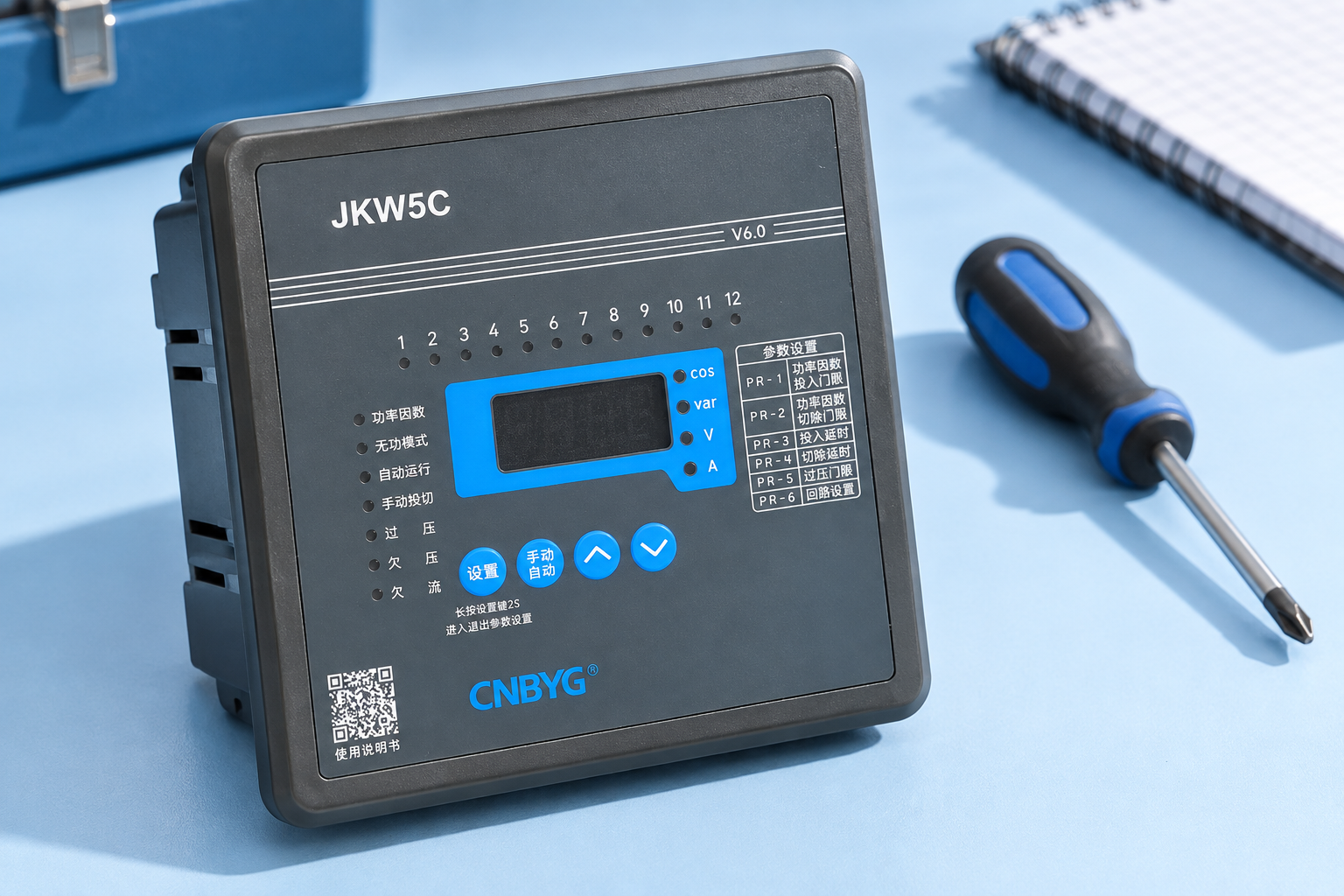
For CNBYG JKW controllers, provide CT ratings, actual stage output, system voltage, stage sequence and load behavior when requesting setup assistance. Ask which C/K convention the offered model uses and record that answer in the commissioning documents.
Further learning
Watch Lecture – 15 Power Factor by nptelhrd
The NPTEL lesson explains reactive power and power factor. It supports understanding of the calculation inputs, while the device manual determines the final menu convention.
أسئلة متكررة
Is Q divided by voltage the final C/K value?
Not by itself. Three-phase current needs the correct √3 relationship and units, CT scaling must be included, and the controller’s response coefficient or menu convention must then be applied.
Can I copy C/K from an identical-looking controller?
Only after confirming the same model convention, CT ratings, stage output and system conditions. Similar front panels do not establish equal configuration requirements.
Will lowering C/K fix poor power factor?
Not necessarily. Measurement errors, insufficient or oversized stages, wrong timing and harmonic distortion require different actions. Diagnose the actual cause before changing sensitivity.
When should the value be reviewed?
Review it when the CT setup, smallest stage, voltage assumptions, stage availability or controller configuration changes, and when logs indicate unexplained insensitive control or excessive switching.