

إلى حساب القدرة غير الفعالة, ، طابق الصيغة مع القراءات التي لديك مسبقاً: استخدم $Q = P \times \tan(\arccos(PF))$ عندما تكون الكيلوواط ومعامل القدرة معروفين، أو أوجد ضلّع المثلث الناقص باستخدام $Q = \sqrt{S^2 - P^2}$ عندما تكون الكيلوولت-أمبير والكيلوواط معروفة. تستعرض هذه الصفحة هذين المسارين للمحطة، ثم فخ الأحاد وثلاثي الطور، ثم ما يجب فعله برقم الكيلوڤار.
ما هي مدخلات العداد التي تحتاجها قبل أي معادلة
اختر الصيغة من الأعمدة الموجودة على المسجل أو الفاتورة، وليس من “معادلة صحيحة واحدة” محفوظة عن ظهر قلب.”
| ما لديْكَ بالفعل | عائلة الصيغ المراد استخدامها | ما تسعى لحله |
|---|---|---|
| القدرة الفعالة P (كيلوواط) ومعامل القدرة | Q = P × tan(arccos(PF)) | قدرة غير فعالة تفاعلية |
| القدرة الظاهرية S (كيلو فولت أمبير) والقدرة الفعالة P (كيلوواط) | س = √(س² − پ²) | قدرة غير فعالة تفاعلية |
| جهد الجذر التربيعي المتوسط، تيار الجذر التربيعي المتوسط، ومعامل القدرة (أو φ) | Q = V I sinφ (1φ) or √3 U I sinφ (3φ) | الطاقة التفاعلية الحالية من الأجهزة الكهربائية |
إذا كان المغذي غنياً بالتوافقيات، فإن معامل القدرة (cosφ) المذكور على لوحة البيانات يُعد بديلاً ضعيفاً للقدرة غير الفعالة (Q) المقاسة. استخدم جهاز جودة طاقة يقيس بالكيلوvar مباشرة عندما لا يكون الشكل الموجي موجة جيبية نقية.
بالنسبة لمعنى أعمدة P / Q / S نفسها، انظر القدرة الفعالة مقابل القدرة غير الفعالة. تبقى هذه الصفحة على الحساب.
اكتب الحد على ورقة العمل قبل الأرقام: لوحة المفاتيح الرئيسية، أو قضيب توزيع المحركات (MCC)، أو محرك كبير واحد. إن خلط تلك الحدود هو كيف تنتج معادلة نظيمة قيمة كيلووار غير صالحة.

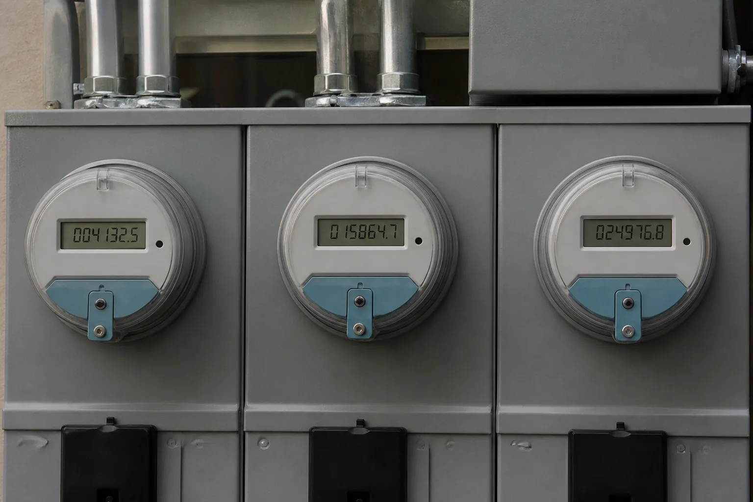
حساب القدرة غير الفعالة (Q) من الكيلوواط (kW) ومعامل القدرة
عندما يقوم مسجل البيانات بطباعة الكيلوواط ومعامل القدرة بالفعل، استخدم مسار ظل المحور (تان).
معامل القدرة هو القدرة الفعالة مقسومة على القدرة الظاهرية. بالنسبة للإزاحة الجيبية، تكون هذه النسبة هي cos φ، إذن φ = arccos(PF) و Q = P × tan φ.
حسابات على طريقة المصانع: مغذي محرك يسحب 56 كيلوواط بمعامل قدرتُه 0.86. إذن $\varphi = \arccos(0.86)$، $\tan \varphi \approx 0.59$، و $Q \approx 56 \times 0.59 \approx 33$ كيلو فولت أمبير تفاعلي.
يعمل المسار نفسه لحافلة كاملة إذا كانت P و PF هي القيم التي تنتمي إلى تلك الحافلة، وليست لوحة بيانات محرك واحد بينما تكون الأحمال الأخرى قيد التشغيل.
ضع في اعتبارك الإشارة. الأحمال الحثية المتأخرة تأخذ قدرة غير فعالة (Q) موجبة حسب الاصطلاح المعتاد في المحطات. التيار السعوي المتقدم يطرح.
إذا كان المطبوع الوحيد هو الكيلوواط واتجاه معامل القدرة من ملخص المرافق للشهر الماضي، تعامل مع معامل القدرة هذا على أنه متوسط شهري، وليس لقطة لأعلى حمل. أعد الحساب بفترة مسجلة تتطابق مع القرار الذي أنت على وشك اتخاذه.

حساب القدرة غير الفعالة (Q) من كيلو فولت أمبير (kVA) والكيلو وات (kW)
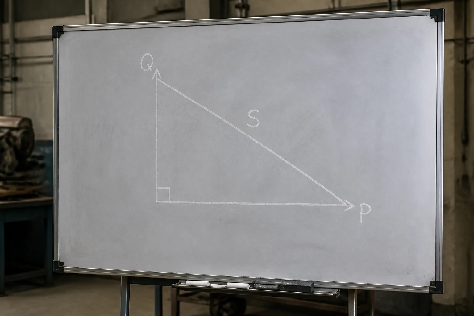
عندما يتم تقييم المحول أو نظام الطاقة غير المنقطعة (UPS) بالكيلو فولت أمبير (kVA) ويظهر عداد العملية الكيلوواط، استخدم مثلث القدرة.
القدرة الظاهرية هي الوتر. القدرة غير الفعالة هي الضلع المتبقي: Q = √(S² − P²)، بشرط أن تكون S ≥ P.
باستخدام نفس المغذي: القدرة الظاهرة $S = 65\text{ kVA}$ والقدرة الفعالة $P = 56\text{ kW}$ تعطي القدرة غير الفعالة $Q = \sqrt{65^2 - 56^2} \approx 33\text{ kvar}$. وهذا يتطابق مع ناتج طريقة الظل ويُعد طريقة مفيدة للمطابقة المتبادلة.
إذا كان S أصغر من P على الورق، فإن المدخلات لا تنتمي إلى نفس الحد. قم بإصلاح نقطة القياس قبل إلقاء اللوم على الصيغة.
قصير صيغة القدرة غير الفعالة مجموعة واحدة تكفي: Q من sin φ عندما يكون لديك V و I، Q من tan φ عندما يكون لديك P و PF، Q من المثلث عندما يكون لديك S و P.
القدرة الظاهرية على لوحة بيانات وحدة طاقة عدم الانقطاع (UPS) هي حد أقصى وليست قراءة لحمل مستمر. قم بربطها بالكيلوواط المقاسة للعملية فقط عندما تكون وحدة طاقة عدم الانقطاع (UPS) هي الحد الذي تنوي تصحيحه.
معاملات الخط أحادي الطور مقابل ثلاثي الطور
يظهر عامل الجذر التربيعي لـ 3 (√3) ثلاثي الطهد فقط عندما تقوم ببناء القدرة غير الفعالة (Q) من جهد الخط وتيار الخط في دائرة ثلاثية الأطوار متوازنة.
| دائرة | شكل القدرة التفاعلية (جيبية) |
|---|---|
| أحادي الطور (طور-محايد) | Q = V I sin φ |
| أحادي الطور (بين طور وطور) | Q = U I sin φ |
| ثلاثي الطور متزن (3 أسلاك أو 3 أسلاك + محايد) | Q = √3 U I sin φ |
U هو جهد الخط للخط. V هو جهد الخط المتعادل. I هو تيار الخط. φ هو زاوية الطور بين الجهد واليار بناءً على ذلك التعريف.
لا تضرب نتيجة $V I \sin\varphi$ أحادي الطور في $\sqrt{3}$ “لجعلها ثلاثية الطور”. ابدأ من صف الطور الثلاثي بدلاً من ذلك.
تيار لوحة البيانات على محرك ثلاثي الأطوار هو تيار خطي. اربطه بجهد خط-إلى-خط وصفّ الأطوار الثلاثة، أو استخدم مسار القدرة/معامل القدرة وتخطَّ الجهد والتيار تماماً.
باختصار، بالنسبة للدائرة أحادية الطور (طور-إلى-المحايد)، $Q$ تساوي $V$ مضروبة في $I$ مضروبة في $\sin \varphi$. أما بالنسبة للدائرة ثلاثية الطور المتوازنة، فالصيغة الخطية هي $Q$ تساوي الجذر التربيعي لثلاثة مضروبة في $U$ مضروبة في $I$ مضروبة في $\sin \varphi$.
إن مُصمّع اللوحات الذي ينسق صيغة واجب منزلي أحادي الطور على مَغْذي ثلاثي الطور دون عامل الثلاثة أطوار، سيقلل من قيمة القدرة التفاعلية (Q) ويصغر حجم كل تحويل للمكثفات يليه.
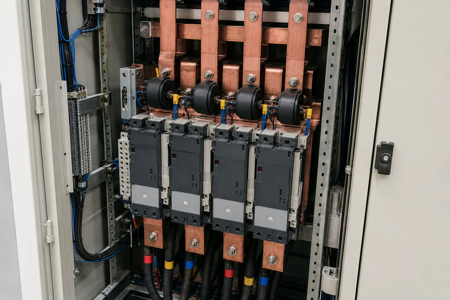
الأخطاء التي تضخم أو تلغي الشحنات المختلطة
تخفق الجبر في الميدان عندما تُدمج الأحمال ذات عوامل القدرة المختلفة بالطريقة الخاطئة.
لا يمكنك جمع مقداري القدرة الظاهرية والتعامل مع المجموع على أنه مسار للقدرة غير الفعالة الكلية. القدرة الظاهرية ليست كمية قياسية تجمعها عندما تختلف الزوايا.
من الميدان: على سْتَكْ إِكْسْشِنْج لِلْهَنْدَسَةِ الْكَهْرَبَائِيَّةِ, تكشف الإجابات عن نفس فخ الامتحانات: جمع قيم القدرة الظاهرية المطلقة لا يوصلك إلى أي نتيجة، والقدرة غير الفعالة المتقدمة تلغي المتأخرة. اجمع القدرات الفعالة والقدرات غير الفعالة ذات الإشارات، ثم أعد بناء قيمة القدرة الظاهرية من مثلث القدرات إذا احتجت إلى إجمالي الكيلوفولت أمبير.
قسمة الكيلوواط على معامل القدرة تنتج كيلو فولت أمبير وليس الكيلوڤار (kvar). إذا كنت بحاجة إلى القدرة غير الفعالة Q بعد تلك الخطوة، فلا تزال تأخذ الجذر التربيعي لـ (S² − P²) أو P × ظتا(جتا⁻¹(معامل القدرة)).
المكثف Q ليس فيزياء ثالثة خاصة. بالنسبة لفرع مكثف، Q = V I sinφ مع تيار متقدم، أو Q = I² Xc مع مفاعلة المكثف. سؤال المنشأة عادة هو كمية الكيلوفار المتقدمة التي يضخها البنك عند الجهد الاسمي، وهي تصنيف كيلوفار في ورقة البيانات عند جهد محدد.
بعد اختيارك للمكثف، السؤال هو: هل تختار ΔQ أم حل مولد القدرة غير المتزامنة الثابت (SVG)؟
تعرض قيم القدرة الغير فعالة (Q) إجابة على سؤال: “كم تطلب هذه الحدود حالياً من الكيلو فولت أمبير التفاعلي؟” وهي ليست بعد قائمة بالمخزون أو المواد.
إذا كان الهدف هو رفع معامل قدرت متأخر وثابت نسبياً، فإن الحسابات التالية هي الفرق بين القدرة غير الفعالة الحالية $Q$ والقدرة غير الفعالة المستهدفة $Q$. وتتم تغطية مشكلة تغير القدرة غير الفعالة هذه ($\Delta Q$) في حساب حجم مجموعة المكثفات لتصحيح معامل القدرة, وتقع عائلات الأجهزة على مُعَوِّض القدرة غير الفعالة محور.
إذا كان Q يتأرجح مع آلات اللحام، أو الرافعات، أو خطوط الدفعات، فقد يتحرك البنك المحول ببطء شديد. ثم ينتقل الحوار إلى مُولِّدات القدرة غير الفعّالة الساكنة (SVG).
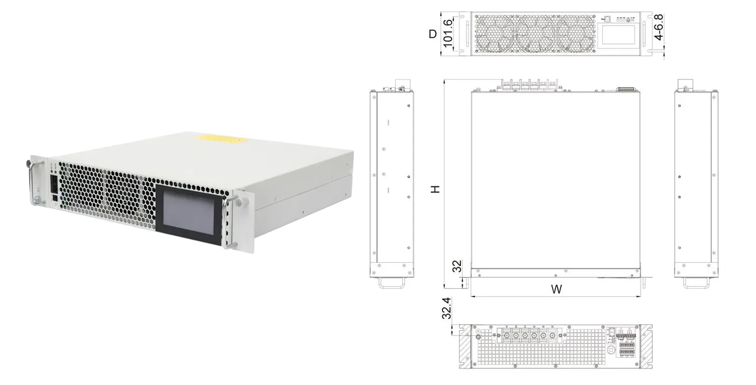
تُدرج صفحة منتج SVG نطاق جهد كهربائي يتراوح بين 230 و690 فولت، وزمن استجابة أقل من 10 مللي ثانية، ومعامل تعويض يزيد عن 95%، وكفاءة تزيد عن 97%. وتصف هذه الأرقام محتوى صفحة المنتج المذكورة. وهي لا تحل محل دراسة الموقع أو حساب Q المذكور أعلاه.
استخدم الكفار (كيلو فولت أمبير التفاعلي) المحسوب لإحاطة المورد باختصار. لا تتخطَ فحص المدخلات وتطلب حجم خزانة بناءً على لوحة بيانات محرك واحد بينما يتم تجاهل باقي الناقل (الباص). أعد تشغيل نفس العمليات الحسابية بعد تغيير العملية قبل أن يقوم أي شخص بتحرير أمر شراء.
الأسئلة الشائعة
كيف تجد القدرة غير الفعالة؟
اقرأ أياً من P و S و PF و V و I التي تثق بها مسبقاً عند حدود واحدة. ثم استخدم الصف المطابق في جدول الإدخال أعلاه.
إذا كان العداد يطبع بالفعل كيلو فولت أمبير تفاعلي (kvar)، فاعتبر ذلك هو القياس واستخدم الصيغ فقط للتحقق المتقاطع.
ما هي المعادلة التي تحسب القدرة الغير فعالة؟
الأشكال الشائعة للقدرة النباتية (أو الكميات النباتية) هي $Q = P \times \tan(\arccos(PF))$، و $Q = \sqrt{S^2 - P^2}$، و $Q = V I \sin\varphi$ (مع وجود $\sqrt{3}$ في كميات خط الثلاث مراحل المتوازن).
هما نفس مثلث القدرة ولكن مكتوبان لمعالجة قيم معلومة مختلفة.
القدرة غير الفعالة
هو المكون المتذبذب الذي يحافظ على المجالات المغناطيسية أو الكهربائية ويُقاس بالفار أو الكيلوفار. للمقارنة بلغة بسيطة مع الوات والفولت-أمبير، استخدم القدرة الفعالة مقابل القدرة غير الفعالة مقال.
كيف يمكنني حساب القدرة غير الفعالة للمكثف؟
عند جهد وتيار RMS معروفين مع تقدم بنسق 90 درجة، Q = V I. مع المفاعلة، Q = I² Xc أو Q = V² / Xc لمكثف مثالي.
توضح لوحات بيانات المكثفات عادة القدرة بالكيلو فولت أمبير التفاعلي (kvar) عند الجهد المقنن؛ ويجب خفض التصنيف إذا كان جهد القضبان الفعلي مختلفاً.
معادلة القدرة غير الفعالة في نظام ثلاثي الأطوار هي: $$Q = \sqrt{3} \times V_L \times I_L \times \sin(\theta)$$ أو باستخدام القدرة الفعالة والزاوية: $$Q = P \times \tan(\theta)$$ حيث: * **$Q$**: القدرة غير الفعالة (بـ VAR أو kVAR). * **$V_L$**: جهد الخط (Line-to-Line Voltage). * **$I_L$**: تيار الخط (Line Current). * **$\theta$**: زاوية الإزاحة بين الجهد واليار (Power Factor Angle). * **$P$**: القدرة الفعالة.
بالنسبة لكميات الخط المتوازنة ثلاثية الطور، Q = √3 × U × I × sinφ، حيث U هو جهد الخط بين الخطوط.
تتخطي العديد من المحطات هذه الخطوة وتحسب الطاقة غير الفعالة (Q) من القدرة الفعالة (kW) ثلاثية الأطوار ومعامل القدرة (PF) بدلاً من ذلك.
هل يمكنني جمع الكيلو فولت أمبير (kVA) لحملين للحصول على القدرة غير الفعالة (Q) الإجمالية؟
اجمع القدرات الفعالة والقدرات غير الفعالة الموقعة. أعد بناء القدرة الظاهرية من الإجماليات فقط عندما تحتاج إلى |S|.
الأحمال الحثية والسعوية المختلطة تلغي بعضها البعض جزئياً في القدرة غير الفعالة (Q) حتى وإن كانت كل قيمة |S| تبدو كبيرة.