

How to calculate power factor starts with one ratio: real power in kilowatts divided by apparent power in kilovolt-amperes from the same metering interval. Use that result to judge feeder current and capacity before you size correction. This article walks the power factor formula, the power triangle, three-phase voltage and current inputs, plant meter registers, logging caveats, and when a dynamic SVG fits next.

Power Factor Formula: PF = kW ÷ kVA
Power factor equals real / active power divided by apparent power when both readings cover the same interval.
The power factor formula is PF = kW ÷ kVA. Keep units consistent so both values are in kilo-units or both are in watts and volt-amperes.
A feeder that shows 80 kW and 100 kVA at the same time has PF = 0.80. That number means 80% of the supplied apparent power is real work; the rest is tied up as reactive demand on that interval.
Rearrangements help when one quantity is missing.
| Need | Formula |
|---|---|
| معامل القدرة | PF = kW ÷ kVA |
| القدرة الظاهرية | kVA = kW ÷ PF |
| Real power | kW = kVA × PF |
| القدرة غير الفعالة | kVAR = √(kVA² − kW²) |
Example: 100 kW at PF 0.8 requires 125 kVA. Transformers, generators, and feeders feel that higher kVA even when the process kilowatts look unchanged.
Link this ratio to القدرة الفعالة مقابل القدرة غير الفعالة when your team still mixes watts and VARs on the same whiteboard.
Use the Power Triangle to Relate kW, kVA, and kVAR
For sinusoidal conditions, the power triangle connects real power, reactive power, and apparent power through S² = P² + Q².
If the meter already gives kW and kVA, reactive power is kVAR = √(kVA² − kW²). That value is what capacitor banks or an SVG must offset if you want a higher PF at the same real load.
The angle between the kW side and the kVA hypotenuse is the displacement angle φ. Under clean sinusoids, PF equals cosφ. That identity fails when harmonics distort the current waveform, which is why later logging matters.
When you already know target PF and present kW, you can also estimate the reactive step needed by comparing present kVAR with the kVAR allowed at the target PF. Work the arithmetic from measured kW and kVA first; do not invent a plant result.
For the dedicated Q path from plant meters, use how to calculate reactive power.
Calculate Power Factor from Voltage, Current, and kW
When the display shows voltage, current, and kilowatts but not kVA, build apparent power first, then divide.
For single-phase circuits: kVA = (V × I) ÷ 1000, then PF = kW ÷ kVA. Use RMS voltage and RMS current on the same circuit.
For balanced three-phase power factor work, use line-to-line three-phase line voltage with line current: kVA = (√3 × V × I) ÷ 1000, then PF = kW ÷ kVA. √3 is about 1.732. Equivalently, PF = kW ÷ ((√3 × V × I) ÷ 1000).
Example: 480 V line-to-line, 200 A line current, and 120 kW on a balanced feeder gives kVA = (1.732 × 480 × 200) ÷ 1000 ≈ 166.3 kVA, so PF ≈ 120 ÷ 166.3 ≈ 0.72.
Skip the √3 shortcut when phases are unbalanced or when a power analyzer already reports true kW and kVA. In those cases, trust the analyzer ratio rather than a hand-built V×I estimate.
Read Plant Meter Registers When kVA Is Missing
A plant / utility meter often stores energy and demand registers instead of a live PF tile.
If the same interval records kilowatt-hours and kilovolt-ampere-hours, average PF ≈ kWh ÷ kVAh. If you have kWh and kvarh for that window, average PF ≈ kWh ÷ √(kWh² + kvarh²).
Forum plant work shows why the window matters: one published meter walk-through used 56,640 kWh and 21,280 kvarh in a month to get average PF ≈ 0.936, while peak kW alone still did not reveal PF at the peak.
مهم Match the interval. Peak kW on a bill without a matching reactive or apparent register does not give PF at that peak, and industrial sites should not assume PF = 1 when converting kW demand to kVA or amps — source: https://forums.mikeholt.com/threads/determining-power-factor-to-use-for-load-calculation-from-utility-bills.132045/
| Meter path | Inputs required | مخرجات | احذر |
|---|---|---|---|
| Direct ratio | kW and kVA, same interval | Instant or demand PF | Mixed intervals invalidate the ratio |
| V / I / kW | V, I, kW (√3 if balanced three-phase) | Calculated PF | Unbalance or harmonics skew V×I kVA |
| Energy registers | kWh with kVAh or kvarh | Average PF over the window | Average PF ≠ PF at peak kW |
Procurement and maintenance teams hit this gap when a utility bill lists on-peak kW demand but no PF column. Calculate or measure PF before you convert that kW figure into feeder amps.
Why a Low Calculated Power Factor Raises Plant Current
A low calculated plant power factor raises current for the same real power, which increases copper losses and voltage drop on plant feeders.
At a fixed kW, lowering PF raises kVA, and the supply must deliver more amperes. That is why a site can report PF near 0.6 on some load combinations and still feel ampacity pressure even when the utility does not print a separate PF penalty.
Capacity is the practical stake. Motors, welders, and lightly loaded transformers pull magnetizing vars; the process still needs the same kW, so conductors and transformers carry extra current. Correction that removes those vars reduces apparent demand for the same production output.
Treat “good PF” as a plant target agreed with the utility and the load profile, not a universal law. Many industrial conversations aim near 0.95, and some educational sources call values below that inefficient in many regions, but your tariff language controls billing.
When Calculation Needs True Power Factor Logging
True vs displacement PF matters when nonlinear loads distort current.
Displacement PF follows the fundamental phase angle (cosφ). True power factor uses total real power over total apparent power, including harmonic content. On VFD-heavy or rectifier-heavy feeders, a clean cosφ reading can look acceptable while true PF is lower.
If your hand calculation used fundamental V and I only, treat it as a displacement-oriented estimate. Confirm with a power quality logger that reports true PF when harmonics are present. The logging method itself is covered in تسجيل معامل قدرة الإزاحة مقابل معامل قدرة التشوه.
Do not average unrelated feeder readings into one plant PF number. Calculate per metering point that matches the decision you are making—utility interconnect, main switchboard, or a large motor feeder.
When Dynamic SVG Compensation Fits After You Calculate PF
After you trust the calculated PF, choose correction by how fast and how often the reactive demand moves.
Fixed capacitor stages on the مُعَوِّض القدرة غير الفعالة hub still fit steady lagging loads. Variable industrial loads that swing between inductive and capacitive reactive demand need a faster electronic response.
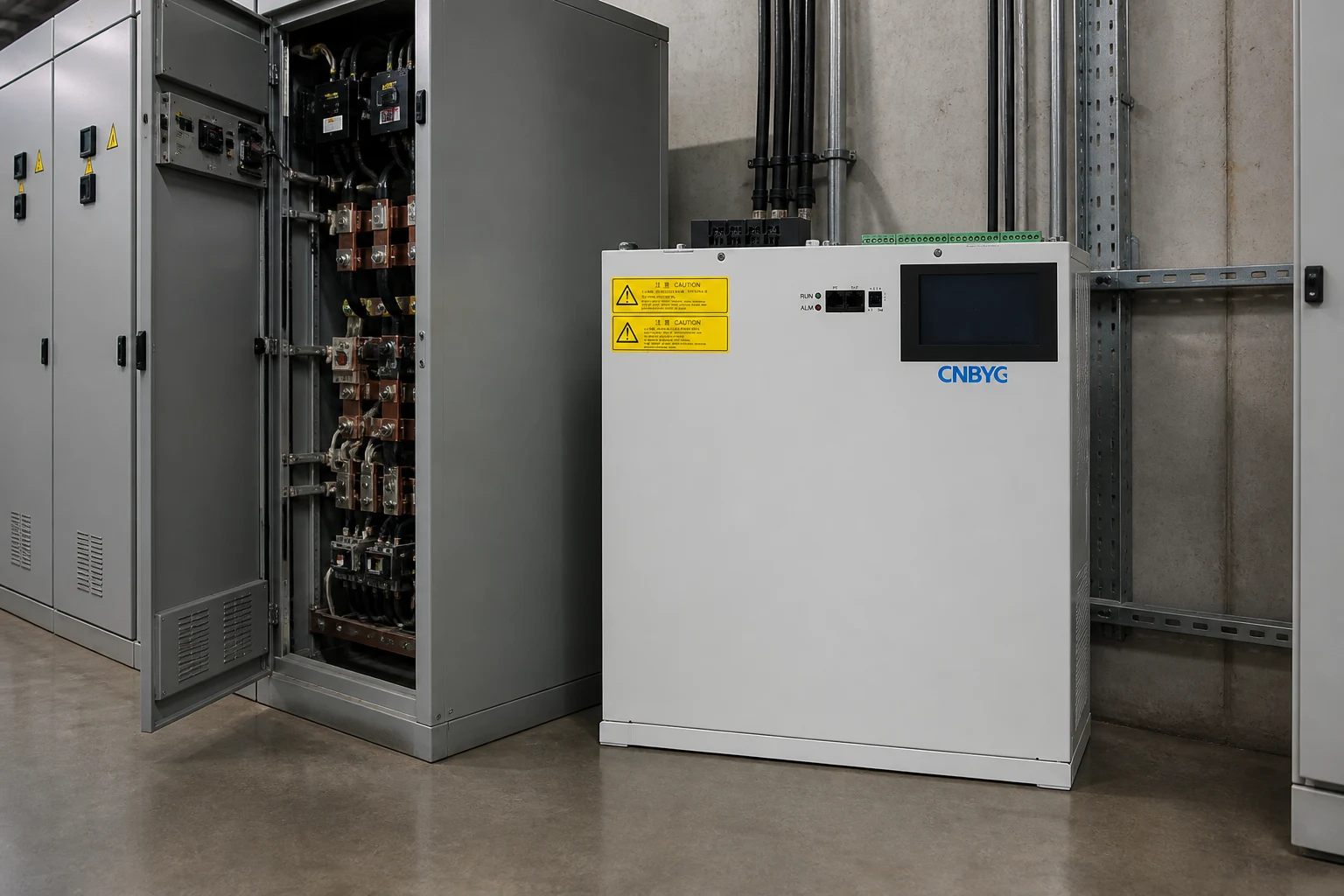
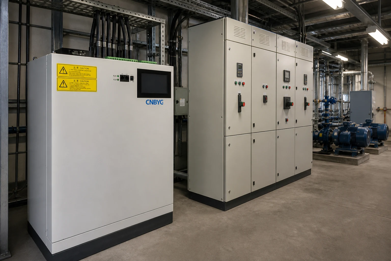
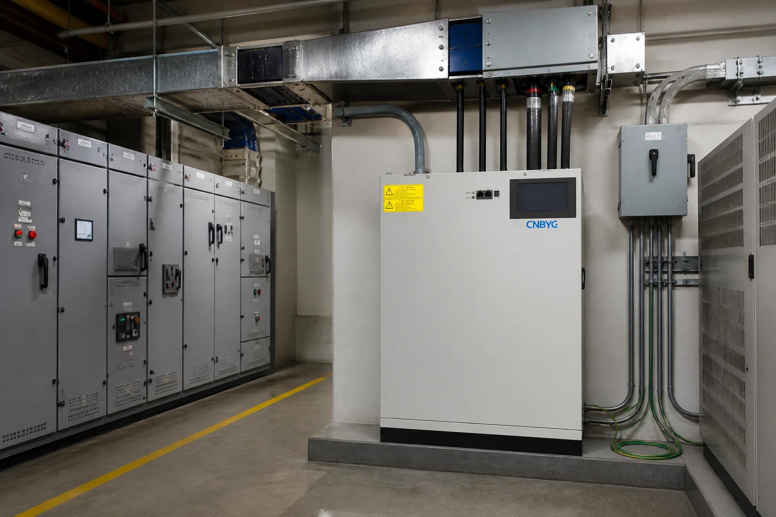
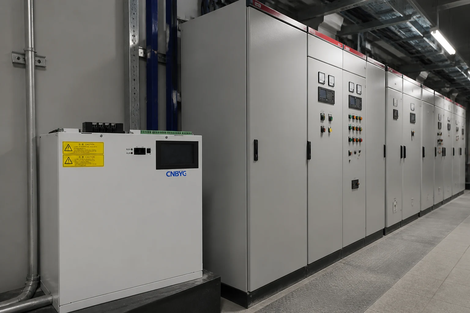
CNBYG SVG static var generators provide that dynamic path. The published wall-mount series covers 230 V, 400 V, 500 V, and 690 V options with kvar capacity choices, response time under 10 ms, compensation factor above 95%, and device efficiency above 97%, with real-time inductive and capacitive reactive support for power-factor correction.
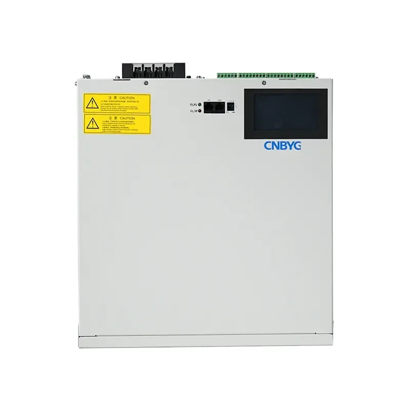
Use the SVG path when measured PF shows persistent reactive swings that fixed banks cannot track cleanly. Stay with meter verification first when you only have a single steady lagging motor feeder and a clear capacitor-bank duty.
Skip SVG selection until PF and load variability are recorded. The product page parameters above are the supported scope; do not treat them as a bill-savings promise.
الأسئلة الشائعة
What is the formula for power factor?
PF = real power ÷ apparent power, usually written PF = kW ÷ kVA when both values use kilo-units from the same interval.
How do I calculate power factor from kW and kVA?
Divide the kilowatt reading by the kilovolt-ampere reading. Example: 80 kW ÷ 100 kVA = 0.80 PF.
How do I calculate three-phase power factor from voltage and current?
For a balanced system, compute kVA = (√3 × line-to-line V × line I) ÷ 1000, then divide kW by that kVA. Use an analyzer true-PF reading when the feeder is unbalanced or distorted.
How can I estimate power factor from utility energy registers?
For one matched window, use PF ≈ kWh ÷ kVAh, or PF ≈ kWh ÷ √(kWh² + kvarh²) when kvarh is available. That average is not the PF at a single peak-kW instant.
What is considered a good power factor?
Many industrial sites target about 0.95 or higher, and some references treat values below that as inefficient in many regions. Confirm the threshold in your utility tariff and interconnection rules.
Why does low power factor increase current?
At the same kW, lower PF means higher kVA, so the feeder current rises. That extra current increases losses and voltage drop without adding useful work.
How is power factor different from reactive power?
Reactive power (kVAR) is the quadrature component in the power triangle. Power factor is the ratio of real power to apparent power; lowering kVAR for a given kW raises PF.
When should I distrust a simple cosφ reading?
Distrust it on nonlinear feeders where harmonics inflate apparent power. Prefer true PF from a power quality logger and compare it with your hand calculation.
المراجع
- معامل القدرة — ويكيبيديا
- What is Power Factor? Formula, Disadvantages & Causes — Circuit Globe
- Determining power factor to use for load calculation from utility bills — Mike Holt Forum
- Plant power factor — Inductive Automation Forum
Humanizer audit: PASS — second pass removed meta-process language; no new facts added beyond Research/Brief; claim IDs kept out of prose.