How to Prevent Capacitor Stage Hunting
Capacitor bank hunting is repeated stage connection and disconnection as the controller moves back and forth around its target. Prevent it by identifying the cause: an oversized minimum stage, rapidly changing reactive demand, unsuitable sensitivity or timing, incorrect CT measurement, wrong stage ratios or deteriorated stage output. Start with a time-aligned operating log, not a guess at a new delay. A longer delay can reduce the operation rate while leaving the underlying mismatch unresolved. The goal is stable, useful compensation within the capacitor and switching-device duty limits.
This guide focuses on APFC capacitor banks with independently switched stages. It distinguishes control hunting from ordinary planned stage changes and complements automatic power-factor-controller settings.
Recognize the actual pattern
A bank that changes stages as production changes is not necessarily hunting. The problematic pattern is repeated cycling that provides little sustained correction, often alternating between undercompensation and overcompensation. Record which stages cycle, how often, the load state and the reactive demand before and after each operation.
Contactor clicks alone do not show the electrical result. Use the controller event log and an appropriate measurement record to connect switching actions with power-factor and reactive-power changes. If the sound comes from a reactor or loose enclosure component, investigate that separately rather than calling all repeated noise controller hunting.
Determine whether the pattern occurs only at light load, after a particular stage connects, following a replacement or during a specific production cycle. These distinctions point to different causes. Preserve the original settings before intervention so later results can be compared with a meaningful baseline.
The minimum stage may be larger than the required correction
Suppose an illustrative load needs about 6 kvar near the chosen target, while the smallest available stage supplies 10 kvar under that operating condition. Connecting it can leave a leading condition; removing it can leave a lagging condition. The controller may alternate because no available stage combination delivers the intermediate correction required.
The numbers illustrate resolution, not a completed design. Voltage, reactor matching and the actual stage arrangement affect delivered output. Review the smallest usable increment and the plant’s light-load reactive demand rather than examining total installed kvar alone.
Adding another large stage does not create a smaller increment. A revised stage distribution or suitable control strategy may be needed. Use capacitor-bank step-size selection to distinguish compensation range from resolution before changing hardware.
Confirm the programmed ratios match the installed bank
The controller’s stage model must represent the physical stage outputs. Equal stages, weighted stages and mixed sizes require the appropriate supported configuration. A wrong ratio list can cause the controller to expect a correction that the commanded stage does not actually deliver.
Compare every output number with the stage drawing, switching device and measured branch response. Capacitor replacements can change output if capacitance or voltage ratings differ, and a detuned branch must be assessed as an assembled combination. Do not rely only on a can’s kvar label.
A failed or disabled small stage can also change useful resolution. The remaining bank may hunt even though it once controlled acceptably. Restore the verified intended arrangement or review the configuration for the actual available stages; do not leave a phantom stage programmed as operational.
Use a root-cause table
| Observed pattern | Candidate cause | Evidence that distinguishes it |
|---|---|---|
| Cycling mainly at light load | Minimum stage too large | Reactive demand and smallest available net stage output |
| Cycling follows a capacitor replacement | Changed output or incorrect stage model | Replacement capacitance, rating convention and measured stage response |
| Cycling during rapid production changes | Load varies faster than the supported control response | Time-aligned load and switching log |
| Commands produce little measured change | Wrong CT position or ineffective stage | Topology and actual branch output |
| All readings are implausible | CT polarity, phase or scaling problem | Exact wiring scheme and equivalent independent measurements |
| Frequent operations near a stable demand | Sensitivity or timing unsuitable | Manual convention, response band and operation history |
| Problem appears after harmonic-load expansion | Changed power-quality or branch conditions | Harmonic spectrum and relevant network study |
These are hypotheses. Confirm the evidence before changing settings. The electricity authority’s APFC specification illustrates the relationship between measurement, configurable response and protection; the installed controller manual governs actual implementation.
Verify the CT measurement loop first
The controller must measure the regulation point where the effect of capacitor switching can be observed. If the bank is outside the CT’s measured path, a valid stage connection may appear ineffective. The controller can then continue changing stages in response to a misleading error signal.
Check CT location, polarity, voltage-phase relationship, input compatibility and ratio convention against the exact diagram. A ratio error affects scaling, while polarity or phase errors affect other aspects of interpretation. Changing sensitivity cannot repair the physical measurement scheme.
Physical CT work must follow the approved qualified-person procedure. An energized secondary must not be left open; the California CT-secondary rule provides a reference. Review APFC CT-ratio setup before diagnosing the controller as defective.
Review sensitivity using the correct C/K convention
A response band that is too narrow can make the controller react to small fluctuations or measurement noise. A band that is too wide can leave meaningful reactive error uncorrected. The appropriate convention depends on the controller and the actual smallest stage and CT ratio.
Do not copy a C/K value from another bank. Calculate the physical stage-current equivalent, then apply the installed manual’s response definition or approved learning method. Confirm whether the setting is a direct current-equivalent value, a coefficient-adjusted threshold or another model-specific quantity.
استخدم APFC C/K calculation to make the assumptions visible. A correct threshold cannot create a missing small stage, and it cannot make incorrect measurements reliable. Treat sensitivity as one part of the loop rather than the first adjustment for every cycling complaint.
Review timing without defeating reconnection protection
Response delay, interval between commands and minimum stage off time serve different functions. Increasing one may reduce reactions to brief load changes; another may protect the capacitor’s reconnection condition. Identify the actual transitions controlled by each parameter before adjusting them.
Keep the manufacturer’s capacitor discharge and switching-device requirements intact. Mechanical contactors should not be forced into fast repeated duty simply because the controller menu allows a short value. Conversely, a very long delay can make the bank appear quiet while leaving sustained demand uncorrected.
ال California capacitor-charge drainage rule is a reference for the discharge arrangement, not a universal reconnection timer. Use the actual equipment documentation for the operational interval and record why each setting was selected.
Do not treat circular switching as a complete cure
A circular sequence can distribute operations among equivalent stages when supported by the controller. It may reduce unequal wear, but it does not improve the smallest kvar increment or repair measurement problems. A bank can hunt while rotating the stage that performs each operation.
Unequal stages need an algorithm that accounts for their sizes. Confirm whether circular selection applies only within equal-output groups or whether a more complex supported method is used. Do not assume the term means the same behavior in every manual.
Record individual stage operation counts where available. A bank-level count can hide one stage receiving excessive duty. If cycling continues after a sequence change, return to the measurement, resolution and load evidence instead of repeatedly selecting different algorithms.
Distinguish distortion-driven PF from reactive-demand cycling
A capacitor bank can improve fundamental displacement power factor without removing current distortion. If the target or operator expectation is based on total power factor from another instrument, additional switching may be requested even when fundamental reactive correction is already adequate.
Compare measurement definitions and harmonic data. The OpenStax AC-power chapter explains the basic sinusoidal relationship, while nonlinear loads require appropriate total-power and distortion assessment. Do not keep adding capacitor stages to chase a metric that the bank cannot control in the intended way.
If stage combinations change distortion or trigger protection, evaluate the branch design and network conditions. A controller-tuning exercise is not a substitute for a harmonic study where that evidence indicates a system-level issue.
Test one correction against the same operating profile
Save a baseline log and a specific hypothesis. If the minimum stage is verified oversized, investigate an approved stage redesign. If CT position is verified wrong, correct the measurement arrangement safely. If sensitivity or timing is the confirmed issue, adjust the appropriate parameter within the documented requirements.
Repeat the assessment under comparable production and light-load conditions. Measure operation frequency, reactive balance, leading intervals and available stage output. A reduction in switching is useful only if correction remains effective and the equipment operates within its intended duty.
Do not judge success from a short quiet period after resetting the controller. Some causes appear only during overnight operation, a particular source configuration or a production cycle. Identify those conditions in the acceptance plan and retain any limitations in the service record.

Decide when a different compensation method is warranted
Where the reactive demand changes too quickly for the installed capacitor bank’s safe response, evaluate suitable fast switching or dynamic reactive compensation. Define the actual load profile and performance objective before selecting a technology. The solution must include voltage, harmonic, thermal, protection and integration requirements.
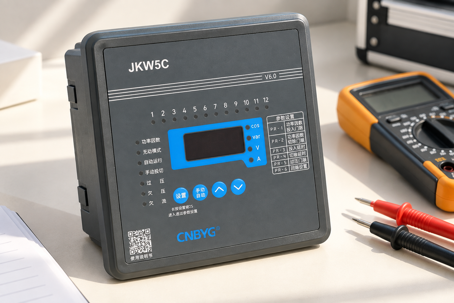
For CNBYG JKW controllers, provide stage sizes, CT details, switching device, timing, sensitivity and a measured event log. Ask for the exact supported sequence and settings for the model. Do not infer suitability from output count or front-panel appearance alone.
Keep the final record focused on the verified cause and measured improvement. State what was corrected, which operating states were tested and whether any stage remains unavailable. Stable compensation means controlled operation with useful correction, not merely silence from the contactors.
Further learning
Watch Lecture – 15 Power Factor by nptelhrd
The NPTEL power-factor lecture explains the correction objective. Use the device manuals and measured load profile for the actual hunting diagnosis and setting changes.
أسئلة متكررة
Is every stage change capacitor-bank hunting?
No. Normal control follows changing demand. Hunting involves repeated cycling that provides little sustained correction or alternates around the target because of a mismatch or unstable control loop.
Will a longer delay always solve hunting?
No. It can reduce operation frequency while leaving oversized stages, measurement errors or poor sensitivity unresolved. Verify that useful compensation remains after any timing change.
Does circular switching stop hunting?
It can distribute duty among suitable stages but does not create finer kvar resolution or correct the measurement loop. Confirm the model’s algorithm and the physical stage arrangement.
What measurements are most useful?
Use a time-aligned record of load state, reactive demand, power-factor definition, stage commands, actual stage response and switching intervals. Add harmonic data where the symptom or plant changes justify it.