


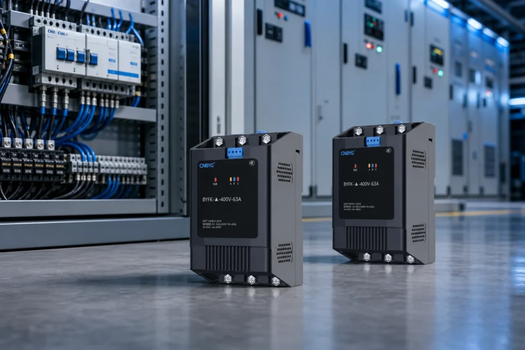
An intelligent compound switch combines mechanical contactors with electronic switching devices to reduce inrush and extend life in capacitor switching applications. This guide focuses on practical evaluation steps for U.S. industrial and commercial buyers—measurement, documentation, and lifecycle support—not generic marketing claims. Where equipment selection is involved, cross-check public specifications on cnbygele.com and confirm project-specific limits with your utility or consulting engineer. Section checklists can be reused as RFQ attachments and commissioning handover outlines.

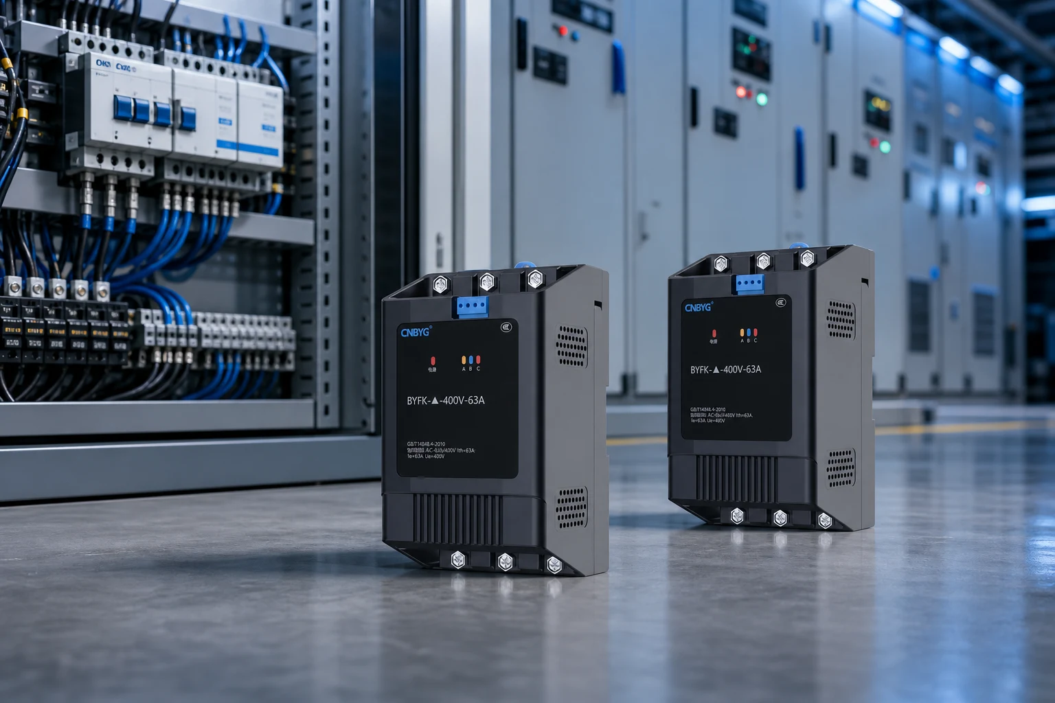
Part 1. Why Switching Stress Matters
Capacitor inrush current stresses contactors and can disturb voltage on sensitive feeders.
Power quality projects succeed when measurement, design, and procurement stay aligned across owner, consultant, and panel builder roles.
Document nominal voltage, available fault level, and ambient conditions before final equipment selection.
Use conservative language for performance claims until site-specific studies confirm targets.
Capture nameplate data, single-line drawings, and utility interconnection rules in the RFQ package to reduce back-and-forth during technical review.
If your site mixes linear motors and nonlinear electronics, treat harmonic and reactive targets as linked requirements rather than separate purchases.
Define acceptance criteria before shipment—power factor, step response, or THD at agreed load points—so commissioning disputes are less likely.
Part 2. Compound Switch Operation
Thyristors engage at zero-crossing, then bypass with contactors for steady-state conduction—reducing arcing and wear.
Compare total installed cost including reactors, controllers, enclosures, and commissioning—not equipment list price alone.
Internal links to SVG product line, low-voltage capacitor banks, and active harmonic filters help buyers navigate related product categories on cnbygele.com.
Lead times and MOQ vary by configuration; confirm in quotation for export shipments.
Capture nameplate data, single-line drawings, and utility interconnection rules in the RFQ package to reduce back-and-forth during technical review.
If your site mixes linear motors and nonlinear electronics, treat harmonic and reactive targets as linked requirements rather than separate purchases.
Define acceptance criteria before shipment—power factor, step response, or THD at agreed load points—so commissioning disputes are less likely.
| Switch type | Inrush | Life expectancy |
|---|---|---|
| Plain contactor | High | Moderate |
| Thyristor switch | Low | High electronics duty |
| Compound switch | Low | Balanced overall |
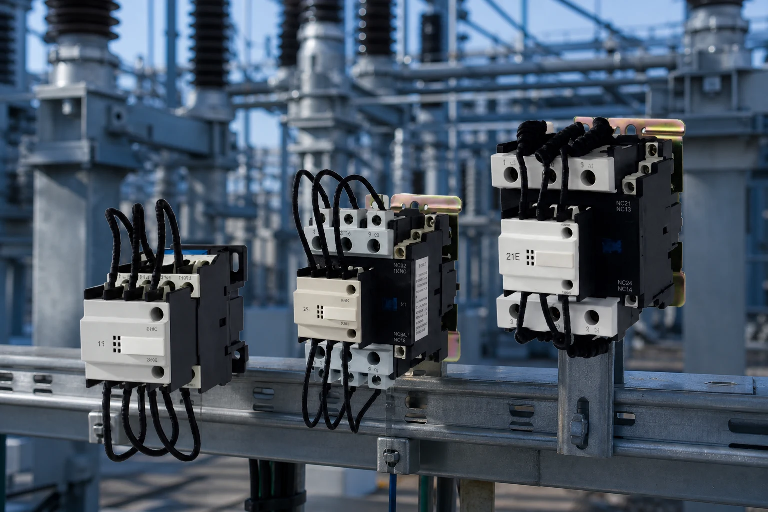
Part 3. Panel Integration
Specify compound switches compatible with your compensation controller outputs and voltage class.
Post-commissioning, schedule periodic verification of power factor, THD, and temperature rise at key buses.
Keep spare fuses, contactors, or modules identified in the maintenance plan.
Submit project parameters via CNBYG contact for engineering feedback on fit and documentation.
Capture nameplate data, single-line drawings, and utility interconnection rules in the RFQ package to reduce back-and-forth during technical review.
If your site mixes linear motors and nonlinear electronics, treat harmonic and reactive targets as linked requirements rather than separate purchases.
Define acceptance criteria before shipment—power factor, step response, or THD at agreed load points—so commissioning disputes are less likely.
Part 4. Documentation and Handover Checklist
Industrial acceptance should not rely on energization alone—documentation proves ratings, safety, and maintainability for the next maintenance cycle.
Use the tables below as a starting RFQ checklist; your utility or EPC contract may require additional items.
For product-specific datasheets, cross-check related CNBYG product pages and request any missing type test excerpts.
Align factory acceptance tests with items your insurer or utility interconnection agreement may require.
When comparing quotations, normalize currency, Incoterms, and included commissioning services before ranking suppliers.
| Document / item | Purpose | When to request |
|---|---|---|
| Factory type test report | Verify rated voltage, kvar, and temperature rise | Before purchase order |
| Single-line diagram template | Panel layout and protection coordination | Design phase |
| Communication register map | BMS/SCADA integration | Before FAT/SAT |
| Spare parts list (5+ year) | Lifecycle planning | Contract negotiation |
| Commissioning checklist | Acceptance testing | Before energization |
| Project stage | Key action | Owner |
|---|---|---|
| Concept | Define voltage class, load list, and utility rules | Owner / consultant |
| Design | Single-line, protection, and communication | Panel builder / EPC |
| Procurement | Verify ratings, tests, and spares | Buyer / QA |
| Commissioning | Functional tests and as-built docs | Site engineer |
Part 5. Commissioning, Monitoring, and Long-Term Operations
Commissioning should verify that reactive and harmonic targets are met at the point of common coupling, not only at the compensation cabinet terminals.
Functional tests typically include step response, power factor at defined load points, and harmonic readings compared to contract or IEEE 519 guidance where applicable.
Monitoring after energization helps catch hunting, unexpected resonance, or capacitor cell failures before they affect production uptime.
Train maintenance staff on lockout/tagout, discharge timing for capacitors, and which alarms require immediate shutdown versus scheduled service.
Schedule a post-warranty review to reassess load changes—production line upgrades often change compensation needs within three to five years.
Utility account managers can clarify whether PF adjustments affect demand charges only, energy charges, or both—align KPIs before writing acceptance tests.
Keep a spare-parts criticality list (fuses, contactors, fan assemblies, control boards) based on lead time and production impact, not catalog defaults alone.
Recommended CNBYG Products
For project support, explore related product line, power quality planning articles, OEM/ODM programs, about CNBYG on cnbygele.com.
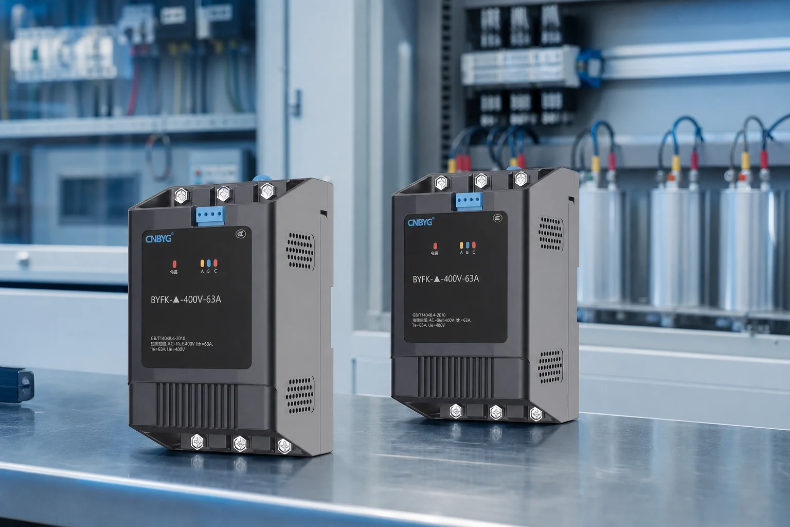
Ready to discuss your project? Contact CNBYG engineering contact with your voltage class, load list, and target power factor or THD goals.
FAQ
What is an intelligent compound (composite) switch?
It is a capacitor switching device that puts a thyristor in parallel with a mechanical contact (often a magnetic-latching relay). Electronics fire the thyristor at the right instant to switch without inrush or arc, while the contact carries the steady-state current with almost no loss.
How does it combine a thyristor and a relay?
On connection, the thyristor conducts first at the voltage zero-crossing to avoid capacitor inrush; then the relay closes and bypasses the thyristor to carry the current with low loss. On disconnection, the relay opens first and the thyristor interrupts the current at its zero-crossing for an arcless break.
How does zero-crossing switching eliminate inrush and arcing?
Closing at voltage zero-crossing means the capacitor sees minimal instantaneous voltage step, so the inrush current stays near rated instead of many times rated. Opening at current zero-crossing means there is no current to sustain an arc, so the contacts do not erode.
Why is a compound switch better than a plain contactor?
A contactor switching a capacitor directly creates large inrush and an arc, which welds contacts and stresses the capacitor. The compound switch limits inrush at zero-crossing and breaks arclessly, greatly extending switching life.
Why not just use a thyristor (SCR) switch alone?
A pure SCR switch avoids inrush but conducts continuously, so it dissipates significant heat, needs a heatsink, and injects some harmonics. The compound switch uses the thyristor only during the brief transient and lets the relay carry steady state, avoiding continuous heat.
Where is the compound switch used in a capacitor bank?
It is the switching element for each capacitor step, in both traditional panels and integrated intelligent capacitors, controlled by the power factor controller to connect and disconnect steps on demand.
Is a compound switch the same as an intelligent capacitor?
No. The compound switch is the switching component; an intelligent capacitor is a complete module that contains a compound switch plus metering, control, protection, and the self-healing capacitors themselves.
References


