


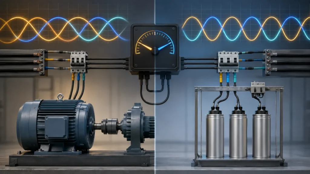
Leading vs lagging current power factor is the phase direction of current relative to voltage: lagging means current peaks after voltage, and leading means current peaks before voltage. That single direction tells you whether the plant is behaving like an inductive load, a capacitive load, or an overcorrected mix. This article compares both conditions, shows where meter signs mislead teams, and maps correction choices that stay on the right side of unity.

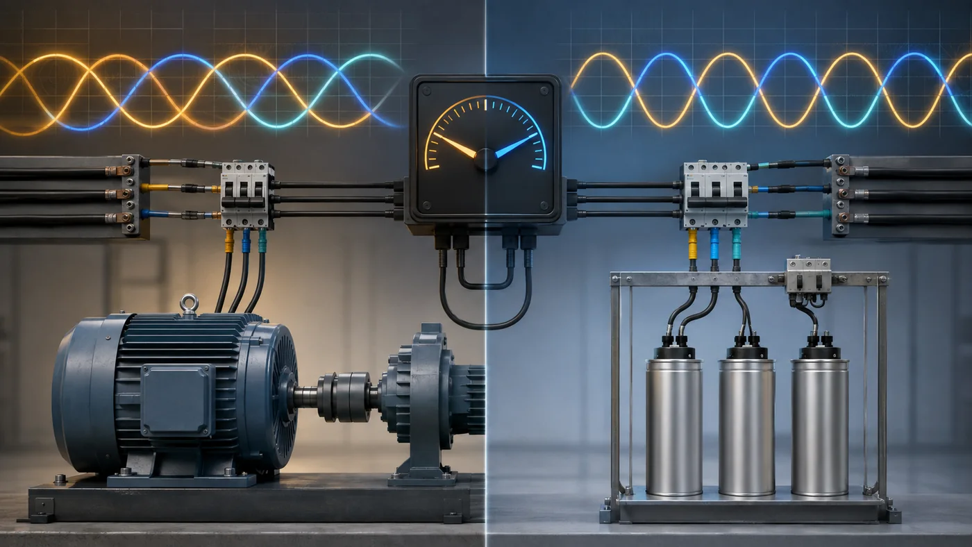
What Leading and Lagging Current Mean at the Meter
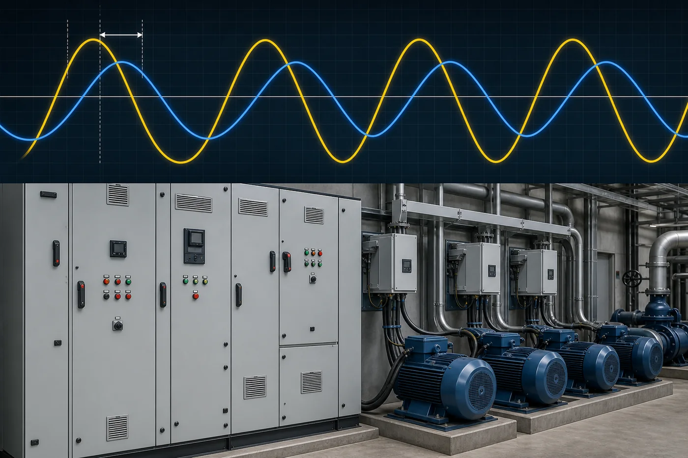
Lagging current reaches its peak after the voltage peak; leading current reaches its peak before the voltage peak. On a phasor diagram with voltage as the reference, lagging current sits behind the voltage arrow and leading current sits ahead of it.
Power factor is the magnitude of that phase relationship, usually written as a number between 0 and 1. The words leading and lagging add the missing direction so operators know which way reactive power is leaning.
In a plant hallway conversation, “0.85 lagging” and “0.85 leading” are not interchangeable. The magnitude looks identical; the correction direction is opposite. Write the direction beside every logged value so the next shift does not reverse the intended fix.
Lagging Power Factor from Inductive Plant Loads
A lagging power factor almost always points to inductive equipment: motors, transformers, and wound coils that draw magnetizing current after the voltage waveform. That delayed current is reactive power the feeder must still carry, even though it does little useful mechanical or thermal work.
Motor-heavy lines show the pattern clearly during production. When conveyors, compressors, or pumps stay online, the plant meter often reports lagging PF because the magnetic fields keep rebuilding every cycle.
Duty changes the severity. Lightly loaded motors can look much worse than the same machines at rated load, so a single snapshot at lunch break is a weak buying input. Log PF across shifts before you size or stage correction.

Leading Power Factor from Capacitive and Overcorrected Systems
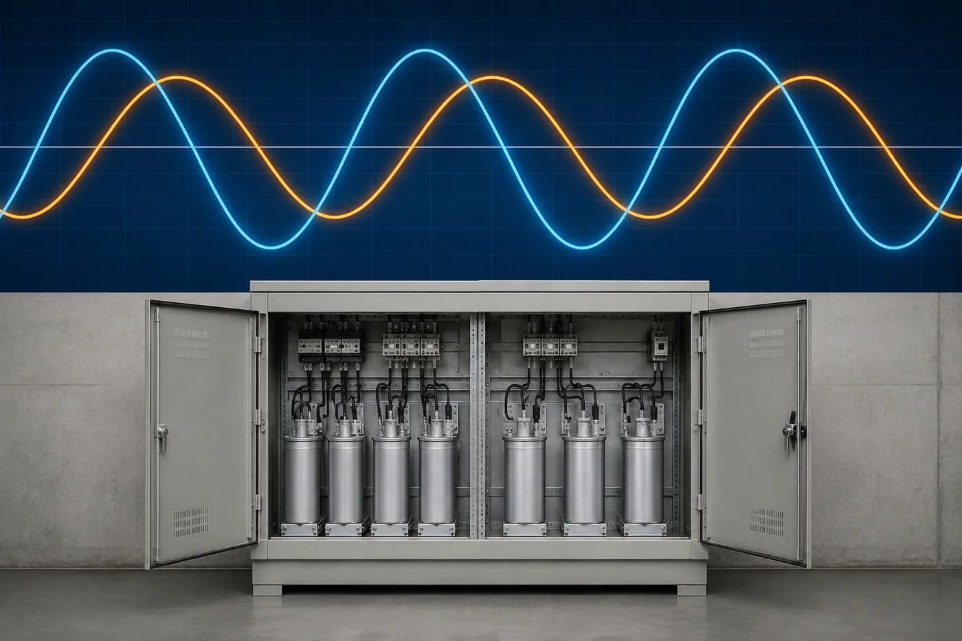
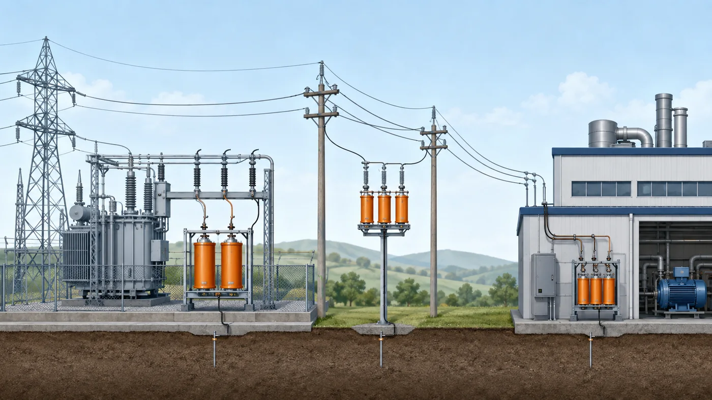
A leading power factor means current peaks ahead of voltage, which is the capacitive side of the ledger. Capacitor banks, long cable capacitance, and excess power factor correction are the usual plant causes.
Overcorrection is the trap. Capacitors added to fix lagging motors can remain online after loads drop, so the same bank that helped at full production pushes the feeder into leading territory at idle.
Important: Field discussions on motor PF correction note that pushing capacitors toward unity is undesirable—practitioners often keep a mildly lagging target because aiming for 1.0 can create a parallel resonant circuit that stresses motors, capacitors, and switchgear after power-off. Source: EEVblog — Capacitor sizing for PF correction.
Some utility tariffs target near-unity PF and disallow leading export to the distribution system. If your interconnection agreement treats leading kvar as a violation, fixed banks that cannot shed with load become a compliance problem, not just an efficiency issue.
Leading vs Lagging Side-by-Side Decision Table
Use the table as a scan tool when engineering and procurement disagree on what the meter “really” said. Match the observed current direction first, then pick the first correction move.
| Decision item | Lagging | Leading |
|---|---|---|
| Current vs voltage | Current peaks after voltage | Current peaks before voltage |
| Typical plant cause | Motors, transformers, coils | Capacitor banks, excess PFC, cable capacitance |
| Reactive behavior | Load absorbs vars | Load supplies vars (capacitive) |
| First correction move | Add staged capacitive support or bidirectional Q | Reduce/shed capacitance or absorb vars |
| Common failure mode | Undersized or never-switched banks | Overcorrection left online at light load |
If both directions appear across a week of logs, you do not have a single static problem. You have a duty-dependent swing that needs switched steps or a bidirectional compensator.
Why Meter Signs Are Not the Same as Lead or Lag
Printed plus or minus on a PF reading follows the meter’s IEEE or IEC sign convention, not a universal law of nature. Lagging still means current behind voltage; leading still means current ahead of voltage.
Teams get stuck when one vendor screen shows a negative PF for inductive load and another shows a positive value for the same condition. The argument is about configuration, not about whether motors suddenly became capacitors.
Before you buy hardware, ask the meter vendor which convention is enabled and whether the display labels lead/lag in words. Keep the words leading and lagging in the work order even if the numeric sign flips after a firmware or setup change.
For logging nuance beyond lead/lag direction, see displacement vs distortion power factor logging. That sibling covers waveform distortion; this page stays on phase direction.
Choose Correction Without Flipping Into the Wrong Direction
Power factor correction should cancel the measured reactive direction, then stop. For a stable lagging plant, staged capacitors or automatic steps that switch with load are the usual first path.
Do not “aim past unity into leading” as a safety margin. Crossing into leading recreates reactive current on the other side and can violate utility rules that forbid exporting leading kvar.
When PF swings with production, prefer equipment that can shed or reverse Q as duty changes. Fixed excess capacitance is the fastest way to convert a lagging problem into a leading problem overnight.
| Plant observation | Prefer | Avoid |
|---|---|---|
| Steady lagging during production | Switched capacitor steps sized to logged duty | One oversized fixed bank |
| Leading after loads drop | Load-interlocked shedding or inductive absorption | Leaving all caps online |
| Rapid lead/lag flips | Bidirectional SVG / dynamic Q | Static overcorrection |
Cluster context for compensation concepts sits on the reactive power compensator hub and the explainer what is reactive power compensation. Capacitor step sizing belongs on capacitor bank sizing for power factor correction, not on this comparison page.
When Bidirectional SVG Compensation Fits Lead/Lag Swings
Choose an SVG when the plant does not stay politely on one side of unity. Welding cells, robot lines, and mixed inductive/capacitive duty can demand lagging support in one minute and leading absorption in the next.
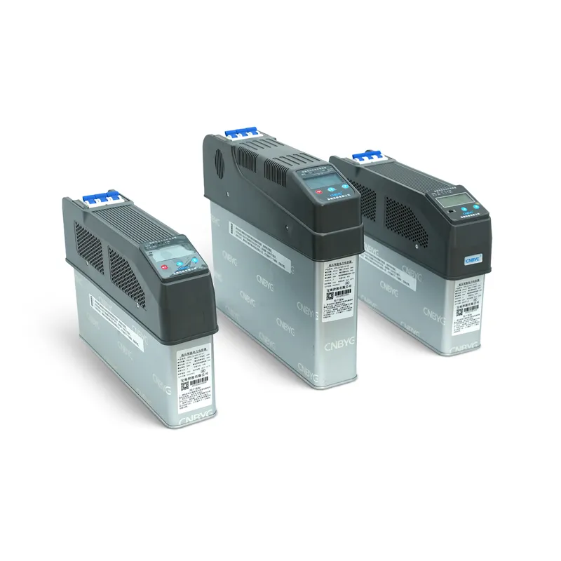
CNBYG SVG Static Var Generators use Infineon IGBT modules with published options from 230 V to 690 V. The product page states response time under 10 ms, compensation factor above 95%, efficiency above 97%, and the ability to compensate both inductive and capacitive reactive power.
That bidirectional Q path is the product fit for this article’s decision: you are not only raising a lagging PF, you may also need to pull a leading PF back without hunting for the next capacitor to switch off by hand.

SVG is not mandatory for every lagging-only plant with a clean duty profile. If logs show a stable lagging condition and switched capacitors already track load without exporting leading kvar, keep the simpler stack and reserve SVG for true bidirectional swings. Procurement should compare published voltage and kvar options against the logged swing range before treating SVG as the default line item.
Verify the measurement before changing compensation
If the controller and analyzer disagree, first compare the same circuit, operating time and power-factor definition. The APFC power-factor reading guide separates CT polarity and phase problems from real leading operation. For repeated stage changes near the target, use the capacitor-stage hunting checks to evaluate measurement, minimum stage size, sensitivity and timing before adding more capacity.
Further learning

Watch Lecture – 15 Power Factor by nptelhrd
FAQ
What is the difference between leading and lagging power factor?
Lagging means current peaks after voltage, usually from inductive loads. Leading means current peaks before voltage, usually from capacitive loads or excess correction.
Is lagging power factor always a problem?
Not automatically. Many plants run mildly lagging without penalty, but low lagging PF raises feeder current and can trigger utility charges once you cross the tariff threshold.
What causes a leading power factor in a plant?
Capacitor banks, cable capacitance, and overcorrected PFC are the common causes. Leading appears most often when capacitive kvar stays online after inductive loads drop.
Does a negative PF reading mean the plant is leading?
No. The numeric sign follows the meter’s IEEE or IEC convention. Confirm whether the display also states leading or lagging in words before you change hardware.
Can power factor correction capacitors create a leading condition?
Yes. Oversizing capacitors or leaving them online after inductive loads drop can push current ahead of voltage. Practitioners often keep a mildly lagging target instead of forcing unity.
When should we consider an SVG instead of more capacitors?
Consider an SVG when logs show rapid lead/lag flips or when you need one device that can source and sink reactive power. Steady lagging-only duty may still fit switched capacitors.
How does leading vs lagging relate to reactive power without calculating kvar here?
Lead/lag tells you the direction of reactive exchange; kvar sizing is a separate calculation task. Resolve direction and duty first, then size equipment on the matching correction page or product sheet.