


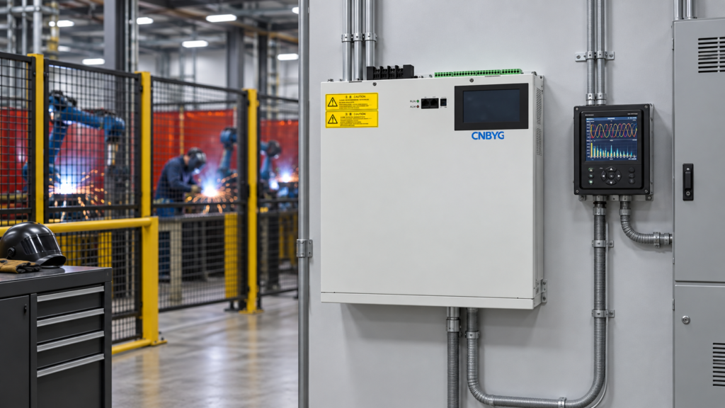
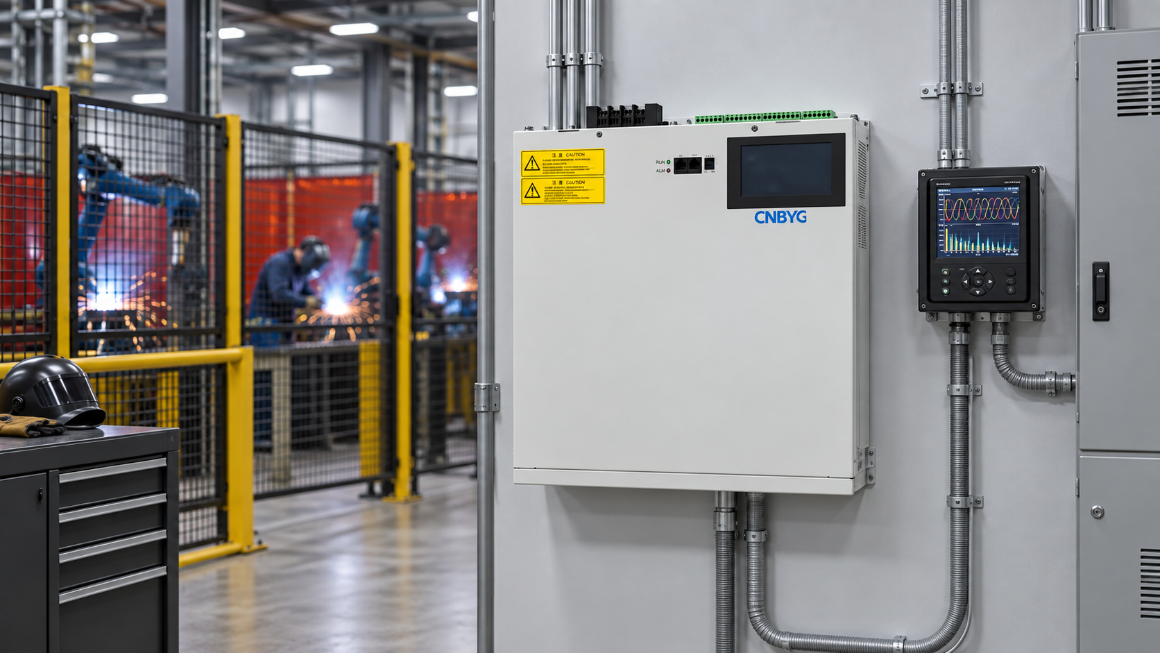
Power Factor Correction for Welding Machines
Power factor correction for welding machines requires a load profile that includes short duty cycles, current pulses, harmonics and idle periods. A welding shop can show a reasonable average power factor while still creating poor instantaneous conditions at the transformer or feeder. The correction plan should define the measurement boundary, distinguish displacement PF from true PF, coordinate capacitors with welders and consider a dynamic SVG when the reactive demand changes too quickly for stepped equipment.
The CNBYG SVG product page provides context for a continuously adjustable compensator. The final capacity, harmonic priority, CT location and protection settings must be based on measured machines and the approved short-circuit and coordination study.
Why welding loads need a different study
Resistance welders, arc welders, robotic cells and inverter welders do not draw the same waveform. Some loads are intermittent; others have a relatively stable cycle but high current peaks. Transformers and cables see the combined result of duty factor, phase distribution, voltage variation and harmonic current. An average reading taken during a break can hide the peak condition that affects the source.
Map each machine, its rated input, process cycle, start/stop behavior, control type and supply phase. Record kW, kvar, voltage, current, PF, THD and individual harmonic orders at the main incomer and at representative welding feeders. Include idle, one machine, several synchronized machines and the maximum production sequence.

Diagnostic decision table
| Welding-shop observation | Likely area | First check |
|---|---|---|
| PF drops only during weld pulses | Short-duration reactive demand or current peaks. | Use synchronized high-resolution traces, not only a daily average. |
| True PF is poor but displacement PF looks acceptable | Harmonic current from power electronics. | Compare both definitions and inspect harmonic spectrum. |
| Capacitor steps switch rapidly | Controller delay is too short for the welding cycle. | Review deadband, minimum on/off time and step size. |
| Voltage dips coincide with welding | Source impedance, transformer capacity or feeder drop. | Measure voltage at the welder and the incomer at the same timestamp. |
| PF changes when robots start together | Cycle synchronization creates a combined peak. | Test the maximum simultaneous sequence. |
| SVG current is high while kvar is modest | Harmonic or unbalance duty is using shared current. | Check priority settings and total RMS current. |
Define PF and the measurement boundary
Ask the utility and plant owner whether the target is displacement PF, true PF, demand PF or a billing-specific value. Welding inverters can have current distortion that makes the true PF lower than the displacement PF. A capacitor may improve the displacement component while leaving the harmonic component largely unchanged.
Mark CT positions on a one-line diagram. A welder-level CT can show an improvement while the main incomer still sees another welding cell, transformer magnetizing current or a harmonic source. Verify CT ratio, phase, polarity, burden and voltage reference with an independent analyzer. The SVG reactive-current compensation guide explains why boundary and sign errors are often mistaken for insufficient capacity.
Choose stepped or dynamic compensation
Fixed or stepped capacitors can suit predictable, relatively slow reactive demand. They need suitable switching equipment, discharge resistors, protection and a minimum on/off time. Welding pulses can be too fast or irregular for the relay to follow. Rapid switching may shorten component life and create an unstable PF trace.
An SVG can respond continuously to changing reactive current and can share current with harmonic or unbalance functions. That shared current must be included in sizing. The grid-voltage and SVG capacity guide explains why the available kvar changes as voltage changes. For high-frequency pulsed loads, assess the control response, current limit and thermal duty rather than assuming the nameplate kvar is available for every function.

Use a hybrid arrangement only when priorities are explicit. A small stepped bank can provide predictable base kvar while an SVG handles variation, but the bank must not switch in response to a transient that will disappear before the stage settles. Define which controller is primary, the deadband, delay, minimum load and fallback.
Size from measured duty cycles
Use synchronized data from the actual production recipe. Calculate the reactive requirement at the selected boundary and convert it to current. For a three-phase system:
[
I_Q = \frac{Q}{\sqrt{3}V_{LL}}
]
Then evaluate total RMS current, harmonic current, unbalance and short-duration peaks. If the SVG has a current priority between reactive, harmonic and negative-sequence compensation, reserve the required share before deciding the nominal size. A welding cell that is idle for most of the hour can still drive a transformer or feeder peak during the active part of a cycle.
Do not size from the average kW of a shift. Use the maximum simultaneous cycle, the lowest voltage and the approved ambient. Include transformer impedance, cable drop and any generator or UPS mode. If the target cannot be met during a pulse, record the limitation and decide whether the solution is additional capacity, a different boundary, feeder reinforcement or process staggering.
Coordinate controls and switching
Set minimum on/off times for capacitor stages and block them during weld start if the switching study requires it. For an SVG, define a target band, leading limit and priority order. Ensure the CT captures the loads the controller is intended to correct. If several welding machines share a bus, confirm that the measured current is not delayed or filtered so heavily that the controller responds to an old cycle.
If a generator supplies the welding shop, verify the generator’s voltage regulator, minimum loading and harmonic tolerance. Transfer events can change the safe correction range. The SVG installation requirements guide covers heat removal, cable entry and service access. The SVG commissioning checklist provides a record structure for CT checks, interlocks, traces and alarms.
Acceptance tests for welding cycles
Acceptance should reproduce the most demanding simultaneous welding sequence. Record synchronized voltage, current, kW, kvar, displacement PF, true PF, THD, harmonic orders, capacitor state, SVG current, temperature and alarms at the incomer and representative feeders. Repeat with one welder, several welders, idle periods and a controlled stop.
Verify that the source does not become leading between cycles, that capacitor steps do not hunt, and that the SVG does not sit at an undocumented current limit. Check voltage dip and recovery at the welder and source. For measurement methods, use the IEC 61000-4-30 catalogue entry as a reference and follow the project instrument specification.
Keep the welding recipe, timestamp, machine state and controller state with each trace. A repeatable acceptance record is more useful than a single PF screenshot because the load changes rapidly.
Common mistakes to avoid
Do not assume a daily average PF represents a pulsed welding load. Do not select capacitor kvar from a motor or transformer study without measuring the weld cycle. Do not let a relay chase each pulse with no minimum time. Do not judge a dynamic compensator only by kvar while ignoring RMS current, harmonic priority and unbalance.
Another error is correcting the welder feeder while the utility meter is affected by several cells and a transformer. Draw the one-line, choose the boundary and verify the CTs before tuning. If the production schedule changes, repeat the study; the previous capacity may no longer cover simultaneous operation.
Preserve a repeatable welding test
Store the welding recipe, machine combination, timestamp, transformer tap, controller state and analyzer settings with every trace. Label the quiet interval between weld pulses as well as the active pulse. This makes it possible to tell whether a capacitor step remained connected after a cycle or whether an SVG reached a harmonic-current limit.
If a new robot, welder or fixture is added, repeat the maximum simultaneous sequence before changing the target. Keep a rollback setting and a safe fallback for communication loss. A short trend with the same recipe on two shifts is more useful than an average from a different production mix. Review the record whenever the transformer, feeder or welding control firmware changes.
Frequently asked questions
Does a welding machine always need a capacitor bank?
No. The need depends on the measured PF definition, duty cycle, utility rule and harmonic content. Some inverter welders need harmonic management more than bulk kvar.
Why does PF look acceptable while the transformer still runs hot?
Harmonic and unbalance current can raise RMS current and losses even when displacement PF looks good. Check true PF, THD and current at the transformer boundary.
Is an SVG suitable for pulsed welding loads?
It can be, when response, current priority, thermal duty and CT placement are validated. Do not assume the full nameplate current is available for reactive support while harmonic filtering is active.
What should the acceptance test reproduce?
The maximum simultaneous welding sequence, individual and combined cells, idle gaps, starts and stops, with synchronized source and feeder voltage, PF, THD, current, controller state and alarms.
Conclusion
Power factor correction for welding machines is a waveform and duty-cycle problem as much as a kvar problem. Measure the real production sequence, define the correct boundary, separate displacement and true PF, and coordinate stepped equipment or an SVG with the welding controls. Validate the result during the hardest simultaneous cycle and the quiet period that follows.
Neutral video: power-factor background
The NPTEL lecture below gives neutral educational context on power factor and reactive power. It is not a product recommendation.
