


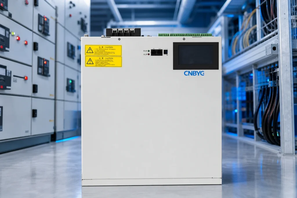
A reactive power compensator improves power factor and voltage support by supplying or absorbing reactive power where the load requires it. This guide focuses on practical evaluation steps for U.S. industrial and commercial buyers—measurement, documentation, and lifecycle support—not generic marketing claims. Where equipment selection is involved, cross-check public specifications on cnbygele.com and confirm project-specific limits with your utility or consulting engineer. Section checklists can be reused as RFQ attachments and commissioning handover outlines. As a cluster anchor, this article ties together measurement, mitigation, and procurement decisions so downstream device guides stay consistent with your site-wide power quality strategy.

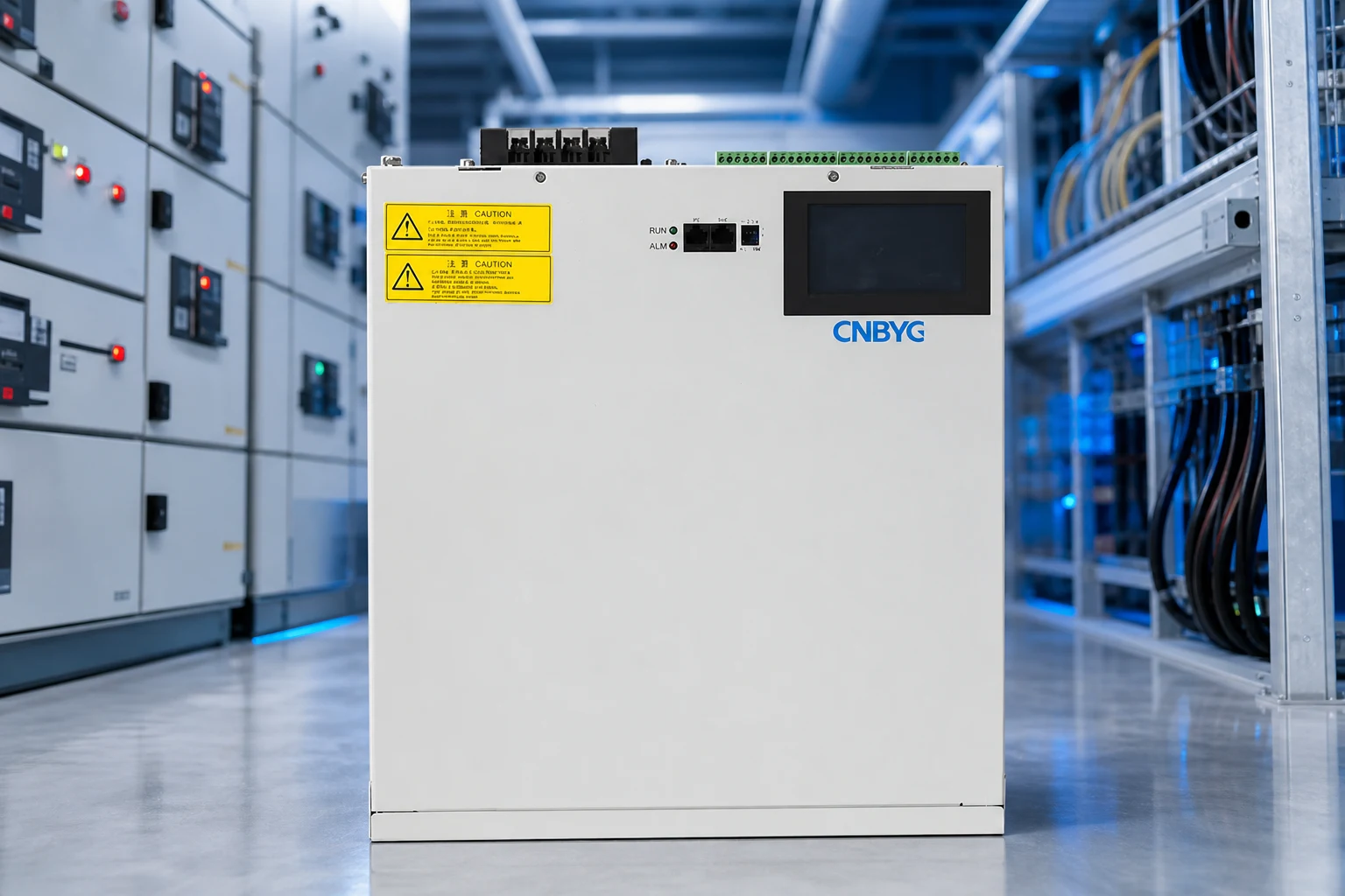
Part 1. Fixed vs Switched Compensation
Fixed capacitors suit constant loads; switched banks track varying power factor.
Reactive power compensation addresses power factor, voltage drop, and transformer loading—not active energy consumption directly.
Utilities may apply demand charges or PF penalties; compensation can reduce billed kVA if aligned with tariff rules.
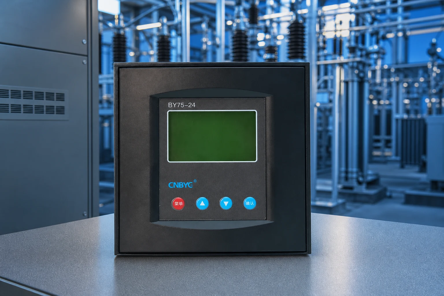
Automatic reactive power controllers switch capacitor steps based on measured reactive power or power factor.
Capture nameplate data, single-line drawings, and utility interconnection rules in the RFQ package to reduce back-and-forth during technical review.
If your site mixes linear motors and nonlinear electronics, treat harmonic and reactive targets as linked requirements rather than separate purchases.
Define acceptance criteria before shipment—power factor, step response, or THD at agreed load points—so commissioning disputes are less likely.
Pillar-level coverage means mapping every major compensator family—fixed and switched capacitors, SVC, SVG/STATCOM, and hybrid stacks—to the load dynamics and grid strength at your site.
Buyers evaluating a whole compensation program should sequence decisions: measure at the PCC, set PF and THD targets, then pick stepped versus dynamic equipment rather than starting from catalog kvar ratings.
Part 2. Dynamic Compensators
SVG compensators respond in milliseconds for arc furnaces, cranes, and weak grids.
Sizing should use interval data from power analyzers rather than nameplate assumptions alone.
Over-compensation raises voltage; under-compensation leaves penalties and thermal stress unresolved.
When load varies within seconds, consider SVG product line instead of rapid capacitor switching that wears contactors.
Capture nameplate data, single-line drawings, and utility interconnection rules in the RFQ package to reduce back-and-forth during technical review.
If your site mixes linear motors and nonlinear electronics, treat harmonic and reactive targets as linked requirements rather than separate purchases.
Define acceptance criteria before shipment—power factor, step response, or THD at agreed load points—so commissioning disputes are less likely.
Cross-functional teams (operations, maintenance, procurement) benefit from a shared glossary: stepped kvar, TDD, flicker (Pst/Plt), and weak-grid voltage support mean different things to different stakeholders.
When several articles in this cluster address individual devices, use this overview to assign owners—who signs off on capacitor banks versus active filters versus SVG—and avoid duplicate purchases on the same feeder.
| Type | Speed | Cost profile |
|---|---|---|
| Fixed cap | N/A | Low |
| Switched bank | Seconds | Medium |
| SVG | Milliseconds | Higher capital |
Part 3. Selection Workflow
Measure → model → simulate switching → commission → monitor quarterly.
Installation must respect clearances, ventilation, and arc-flash labeling per site safety program.
As-built drawings and test records support future audits and insurance reviews.
See CNBYG power quality system options when multiple feeders share compensation goals.
Capture nameplate data, single-line drawings, and utility interconnection rules in the RFQ package to reduce back-and-forth during technical review.
If your site mixes linear motors and nonlinear electronics, treat harmonic and reactive targets as linked requirements rather than separate purchases.
Define acceptance criteria before shipment—power factor, step response, or THD at agreed load points—so commissioning disputes are less likely.
Long-term OPEX often hinges on switching wear, capacitor cell replacement, and filter module cooling; pillar planning should budget spares and training before the first outage.
Part 4. Documentation and Handover Checklist
Industrial acceptance should not rely on energization alone—documentation proves ratings, safety, and maintainability for the next maintenance cycle.
Use the tables below as a starting RFQ checklist; your utility or EPC contract may require additional items.
For product-specific datasheets, cross-check related CNBYG product pages and request any missing type test excerpts.
Align factory acceptance tests with items your insurer or utility interconnection agreement may require.
When comparing quotations, normalize currency, Incoterms, and included commissioning services before ranking suppliers.
| Document / item | Purpose | When to request |
|---|---|---|
| Factory type test report | Verify rated voltage, kvar, and temperature rise | Before purchase order |
| Single-line diagram template | Panel layout and protection coordination | Design phase |
| Communication register map | BMS/SCADA integration | Before FAT/SAT |
| Spare parts list (5+ year) | Lifecycle planning | Contract negotiation |
| Commissioning checklist | Acceptance testing | Before energization |
| Site condition | Risk | Mitigation |
|---|---|---|
| Harmonics present | Resonance with capacitor steps | Detuning reactors or APF per IEEE 519 review |
| Outdoor installation | Temperature / humidity | Confirm enclosure and capacitor technology |
| Frequent motor switching | Inrush and step transients | Proper switching sequence and controller delays |
| Utility PF penalties | Operating cost | Size to measured kvar at billing interval |
Part 5. Commissioning, Monitoring, and Long-Term Operations
Commissioning should verify that reactive and harmonic targets are met at the point of common coupling, not only at the compensation cabinet terminals.
Functional tests typically include step response, power factor at defined load points, and harmonic readings compared to contract or IEEE 519 guidance where applicable.
Monitoring after energization helps catch hunting, unexpected resonance, or capacitor cell failures before they affect production uptime.
Train maintenance staff on lockout/tagout, discharge timing for capacitors, and which alarms require immediate shutdown versus scheduled service.
Schedule a post-warranty review to reassess load changes—production line upgrades often change compensation needs within three to five years.
Utility account managers can clarify whether PF adjustments affect demand charges only, energy charges, or both—align KPIs before writing acceptance tests.
Keep a spare-parts criticality list (fuses, contactors, fan assemblies, control boards) based on lead time and production impact, not catalog defaults alone.
Pillar and planning articles should be reviewed annually against meter logs and utility rule changes.
Export a PDF snapshot after each major edit so field teams and EPC partners reference the same version during outages and retrofits.
Recommended CNBYG Products
For project support, explore our related product line, power quality system options, and OEM/ODM capabilities on cnbygele.com.
FAQ
What is a reactive power compensator?
It is equipment that supplies or absorbs reactive power to correct power factor and support voltage. Types range from fixed and switched capacitor banks to SVC and active SVG/STATCOM systems, chosen by how fast and how continuously the load varies.
What are the main types?
Fixed capacitor banks (steady base load), automatic switched capacitor banks (stepped, controller-driven), SVC (thyristor-controlled, continuous but generates harmonics), SVG/STATCOM (active, stepless, fastest), and hybrid systems that combine capacitors with an SVG.
What is the difference between a capacitor bank, SVC, and SVG/STATCOM?
Capacitor banks correct power factor in steps and respond in seconds. SVC responds in about 2-3 cycles and is continuous but produces harmonics that need filtering. SVG/STATCOM uses power electronics for stepless, millisecond response and can both supply and absorb reactive power.
How fast does each compensator respond?
Switched capacitors respond in seconds (stepped), SVC in roughly 2-3 cycles, and SVG/STATCOM in about 10-15 ms. Exact figures depend on the vendor’s topology and rating.
When should I use a dynamic SVG instead of switched capacitors?
Use dynamic compensation for fast-varying or shock loads (arc furnaces, welders, cranes), for flicker mitigation, and on weak grids, because switched capacitors are too slow and their output drops with voltage while an SVG holds near-constant current.
What is a hybrid compensation system?
A hybrid system uses capacitor banks to cover the bulk, steady reactive demand economically and an SVG to trim the fast, fine, and dynamic component, balancing cost and performance.
Does an SVC or capacitor bank work as well as an SVG on a weak grid?
No. Capacitor and SVC output falls with the square of voltage, so on a weak grid their support weakens just when it is needed. A STATCOM/SVG holds near-constant reactive current down to low voltage, making it better suited to weak grids.
References
- IEEE 1052-2018 — Application guide for STATCOM
- SpecForge — Reactive power compensation types
- Hitachi Energy — STATCOM
- CIRCUTOR — Reactive energy & harmonics products
Ready to discuss your project? Contact CNBYG engineering support with your voltage class, load list, and target power factor or THD goals.


