


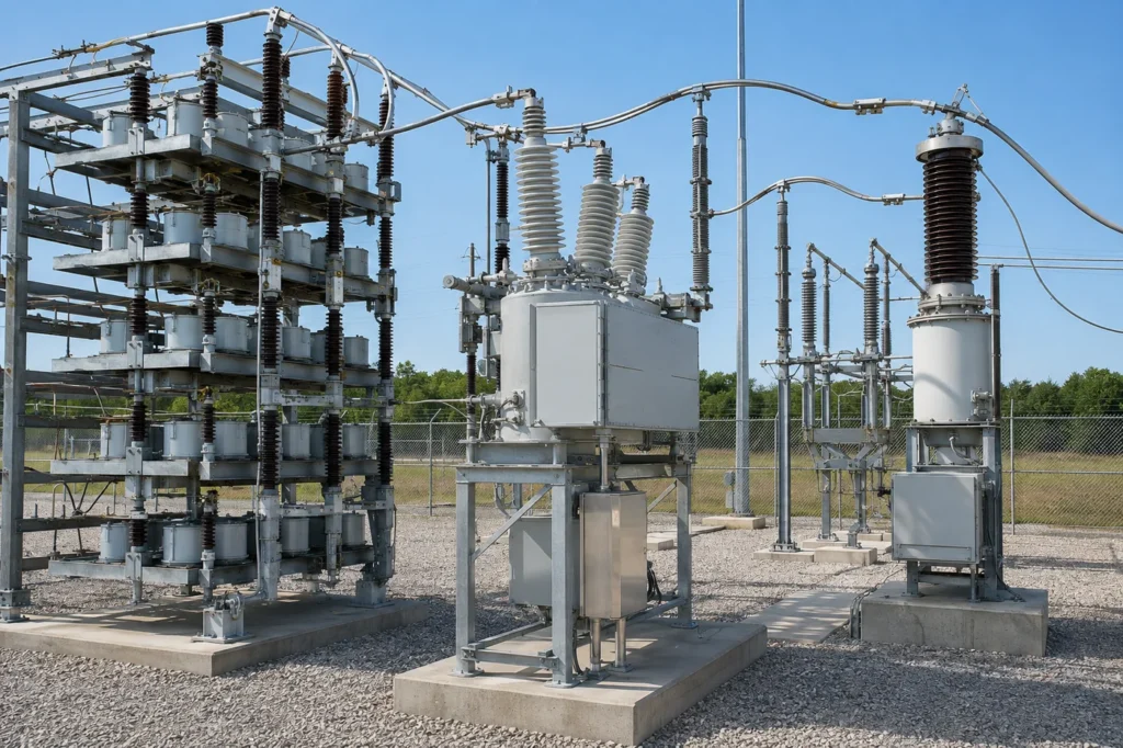
Substation capacitor bank protection combines unit-level fault isolation, bank unbalance detection, phase and ground fault protection, abnormal-voltage supervision, switching control, and breaker coordination. The central objective is to detect a failed element or unit before voltage is redistributed beyond the surviving capacitors’ limits, while remaining secure during normal unbalance and energization transients. The correct functions and settings depend on the bank connection, fusing architecture, series/parallel arrangement, source strength, switching duty, and utility standards.

Protection Starts With the Bank Arrangement
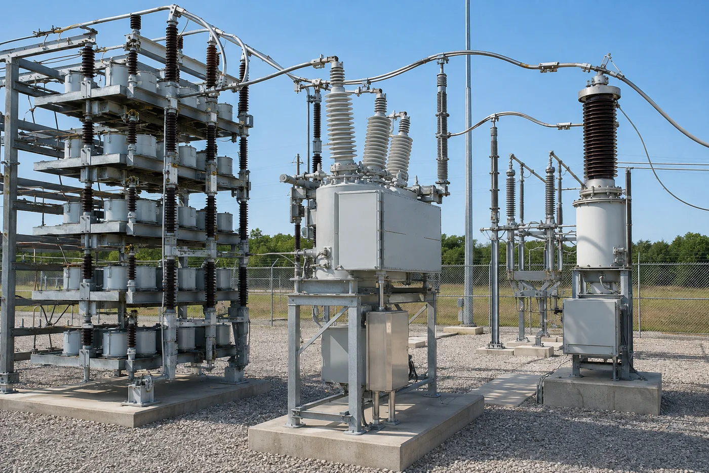
Substation capacitor bank protection cannot be selected from kvar alone. The engineer first maps capacitor elements into units, units into series and parallel groups, and groups into each phase. Connection—grounded wye, ungrounded wye, double wye, bridge, or delta—determines which fault quantities are visible. Available fault current, neutral grounding, instrument-transformer location, and the number of parallel units affect fuse operation. The approved single-line and physical rack drawing must agree, because a relay calculation based on the wrong group arrangement can appear precise while protecting a different bank.
What Must Be Detected
The scheme must respond to internal element or unit failures, phase faults, ground faults where applicable, abnormal unbalance, sustained overvoltage, undervoltage, excessive current, breaker failure, and switching problems. It must also avoid tripping for normal manufacturing tolerance, system voltage unbalance, temperature-related capacitance change, instrument error, and expected transients. Protection is layered: unit fuses may limit damage locally, bank unbalance functions identify capacitance loss, and system relays clear faults beyond the capability of a unit fuse. Alarms should give operators time to act before surviving units exceed their permitted voltage.
Externally Fused, Internally Fused, and Fuseless Banks
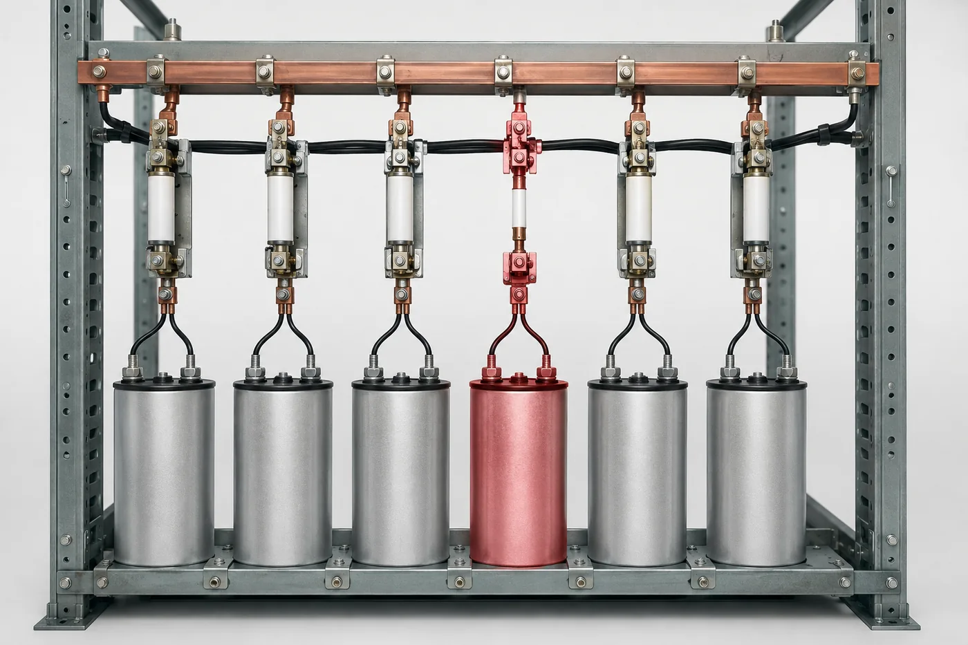
An externally fused bank isolates a complete failed capacitor unit and provides a visible indication. An internally fused unit removes individual failed elements while the unit remains connected. A fuseless bank relies on its series arrangement and unbalance protection as failed elements change the string condition. Each architecture produces a different relationship between failed components and measured neutral or bridge quantity. Relay thresholds and maintenance rules must be derived for that architecture. The detailed fusing comparison explains these differences; protection engineers should not reuse an alarm table from another bank type without recalculation.
Unbalance Protection
Unbalance is the key early-warning measurement for many shunt banks. Depending on connection, the relay may measure neutral current, neutral voltage, phase-voltage difference, current difference between double-wye sections, or bridge differential quantity. Calculate the expected signal for progressive element or unit failures and compare it with normal inherent unbalance. Compensation may be needed for system voltage imbalance and capacitor tolerance. Use separate alarm and trip levels where the design permits continued operation after limited failures. The trip level should protect the remaining elements from unacceptable overvoltage, not merely indicate that symmetry is imperfect.
Overcurrent and Ground Fault Functions
Phase overcurrent functions protect conductors, switches, and the bank against faults that produce sufficient current, but they may not detect a small change in capacitance. Ground protection depends strongly on neutral grounding and system configuration. Settings coordinate with capacitor-unit fuses, upstream relays, breaker capability, transformer protection, and expected energization inrush. Instantaneous elements need security during switching and discharge events; delayed elements must still clear damaging faults. A bank breaker does not replace unit-level protection, and a unit fuse does not replace bank or bus fault protection.
Overvoltage, Undervoltage, and Frequency
Capacitor reactive output varies with the square of voltage, so sustained overvoltage increases dielectric and thermal stress. Protection and control should distinguish a system overvoltage from the voltage redistribution caused by lost units. Undervoltage logic may block switching, trip an isolated bank, or prevent an unwanted re-energization depending on utility practice. Frequency affects capacitor current and can matter during abnormal system conditions. Setpoints and delays belong to the owner’s adopted standards, system study, and equipment ratings. Generic settings from an article cannot replace coordination with regulators, transformer taps, and grid controls.
Switching Transients and Breaker Duties
Energization creates inrush, and back-to-back energization can be severe because an already energized bank supplies high-frequency current into the incoming bank. Breaker restrike can impose damaging overvoltage. Protection studies therefore coordinate switching-device ratings, point-on-wave control where used, surge arresters, series reactors, discharge devices, and relay filtering. A transient should not cause nuisance operation, but relay security must not mask a genuine fault. Review closing scatter, residual charge, dead time, and the operating sequence for multiple steps. Record maximum switching frequency because mechanical and electrical duties accumulate.
Harmonics and Thermal Protection Boundaries
Nonlinear loads can drive harmonic current into a bank or create parallel resonance with system inductance. Overcurrent may show the symptom without identifying the cause. Measure the harmonic spectrum and run an impedance study before adding or uprating a bank in a harmonic-rich network. Check capacitor current, voltage, fuse heating, reactor duty, and relay measurement behavior. Detuned or filtered designs may be required. Protection should alarm or trip abnormal duty, but it cannot make an unsuitable resonance condition acceptable. Use the reactor and harmonic-resonance guides as supporting studies, not substitutes for site measurements.
Relay Setting Workflow
Begin with the final bank drawing and verified equipment ratings. Model normal tolerance and system unbalance, then simulate progressive unit or element failures for every credible phase and group. Calculate surviving-unit voltage, neutral or bridge signal, and bank current. Establish alarm and trip points with measurement error and security margin. Check phase and ground faults, inrush, back-to-back switching, breaker failure, abnormal voltage, loss of station service, and communication failure. Coordinate with upstream and downstream devices. Document calculations, logic equations, timers, blocking conditions, test points, and the permitted operating response after an alarm.
| Protection layer | Primary evidence | Main purpose | Common security check |
|---|---|---|---|
| Unit fuse | Internal fault current | Isolate failed element or unit | Inrush and parallel discharge duty |
| Unbalance | Neutral, bridge, or section difference | Detect capacitance loss | Tolerance and system unbalance |
| Phase/ground fault | CT and residual quantities | Clear bank or connection faults | Switching transient security |
| Voltage supervision | Bus and bank voltage | Limit sustained dielectric stress | Regulator and tap operation |
Commissioning Tests
Commissioning verifies CT and VT ratios, polarity, phase association, wiring, grounding, relay settings, breaker control, interlocks, alarms, trip paths, supervisory indication, and time synchronization. Measure the healthy-bank unbalance baseline and compare it with the calculation. Test simulated alarm and trip quantities without exposing the bank to an actual fault. Confirm discharge and reclose timing, breaker status, local/remote control, and failure behavior. During first energization observe current, voltage step, relay records, waveform disturbance, and abnormal sound. Resolve unexplained differences before accepting normal operation.
Maintenance and Event Review
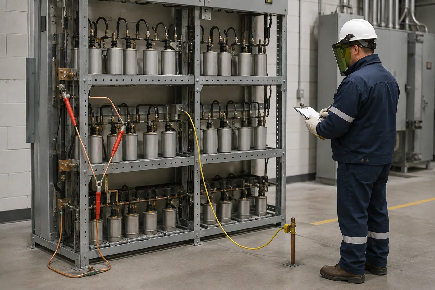
After an operation, preserve relay oscillography, sequence-of-events data, switching command, bus voltage, phase currents, unbalance quantities, and environmental observations. Inspect only after isolation, required discharge time, absence-of-voltage testing, and grounding. Check fuses, bushings, connections, leakage, bulging, contamination, corrosion, wildlife evidence, and reactor condition. Test suspected units using the owner’s procedure. Replacing a fuse and resetting a relay without identifying the failed component or verifying remaining margin can conceal a developing problem. Update the as-maintained failure count and permitted-operation table.
Protection RFQ Checklist
Specify bank voltage, frequency, kvar, connection, element/unit/group arrangement, fusing architecture, neutral grounding, available fault current, insulation level, switching device, existing parallel banks, harmonic environment, instrument transformers, station DC, communication protocol, breaker-failure requirements, owner relay platform, and applicable standards. Require the vendor to provide expected unbalance quantities for staged failures, surviving-unit voltage, fuse coordination basis, recommended alarm/trip limits, discharge requirements, and test documentation. Clarify responsibility for the settings study and field commissioning. CNBYG’s low-voltage compensation products are plant-side equipment; utility medium-voltage protection remains a project-specific engineering scope.
Change-Control Requirement
Any later change to capacitor units, fuse type, series-group population, CT or VT ratio, grounding, switching device, relay firmware, or operating logic triggers a settings review. Even a like-for-like maintenance assumption should be confirmed against drawings and nameplates. Keep the approved calculation, settings file, test report, and as-left values under revision control. Operators should know who may authorize temporary operation after an alarm and which condition requires immediate trip. This discipline prevents a mechanically successful repair from silently invalidating the electrical protection basis.
Related Engineering Guides
Review the substation-bank purpose, fusing architectures, controlled switching, and plant-side compensation products.
FAQ
What is the main protection for a capacitor bank?
No single function is sufficient. Unit fusing, unbalance, overcurrent, voltage supervision, and breaker protection work together.
Why is unbalance protection important?
It can detect lost capacitance before phase current changes enough for ordinary overcurrent protection.
Can settings be copied from another bank?
No. Connection, series groups, fusing, tolerances, ratios, and permitted failed-unit conditions change the calculation.
Does a fuse protect against resonance?
No. Harmonic resonance requires measurement and a network study; a fuse only responds to its assigned abnormal current duty.
What should be saved after a trip?
Relay records, waveforms, sequence of events, switching state, voltage, current, inspection findings, and test results.
References
