

Switchboard integrators should treat SVG commissioning as a sequenced set of installation, control, thermal, and load tests at the defined connection point—not as a single energization after terminations are landed. The handover record should show what was verified de-energized, what was observed at no-load energization, and which partial-load or representative operating states were captured against the approved drawing.
Direct answer
Switchboard integrators should treat SVG commissioning as a sequenced set of installation, control, thermal, and load tests at the defined connection point—not as a single energization after terminations are landed. The handover record should show what was verified de-energized, what was observed at no-load energization, and which partial-load or representative operating states were captured against the approved drawing.
Panel builders inherit problems when SVG modules are treated like passive branches: landed, energized once, and handed over without staged evidence. The commissioning binder should trace each step from torque verification through no-load boot, partial-load var response, alarm checks, and owner witness points. CNBYG can discuss SVG Static Var Generators product-line context when documented SVG integration and commissioning is the defined objective. It cannot establish UL listing approval, a guaranteed power-factor result, or a substitute for the owner acceptance test from an article. See the Power Quality System Engineering Guides for related planning topics.

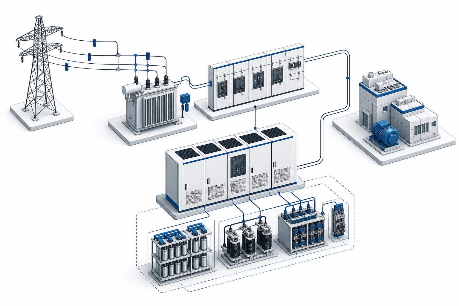
Verify switchboard drawings before energizing SVG modules
Compare the approved single-line, terminal schedules, CT diagrams, and cooling layout against the built assembly while the section is de-energized. Mark torque on main conductors, confirm equipotential bonding paths, and photograph any deviation before covers close. Control wiring deserves the same discipline: polarity, interlock chains, fan enable circuits, and communication drops should match the integrator’s test sheet.
For SVG modules integrated into low-voltage switchboards or compensation assemblies, record which compensation section owns the SVG feeder, whether the module shares a bus with capacitors or filters, and how the owner expects maintenance isolation to work. Missing those notes creates late disputes about who may open which door under load.
| Pre-energization check | Record to keep | Typical failure mode |
|---|---|---|
| Conductor and lug torque | Torque log with tool calibration date | Loose joints under thermal cycling |
| Grounding and bonding | Continuity readings or signed checklist | Noise on control signals |
| Cooling path | Filter condition, duct direction, fan rotation | Early thermal alarm or shutdown |
| CT orientation | Diagram mark-up and photo | Reverse var control at first load step |
Stage de-energized, no-load, and partial-load checks
Commissioning should never jump from wiring complete to full plant load. A practical sequence for integrators:
- De-energized inspection and insulation checks per the project specification.
- Control power applied first; verify PLC or controller boot, network link, and alarm defaults.
- No-load energization to confirm fan operation, door interlocks, and baseline alarms without var output.
- Partial-load steps using agreed test loads or plant sections to observe var response and stability.
- Representative production loading when the owner specification requires it.
Log door interlocks, fan operation, and alarm states at each step because they affect maintenance access and future service. Tie every capture to the commissioning step and switchboard operating mode so the owner can reproduce results.
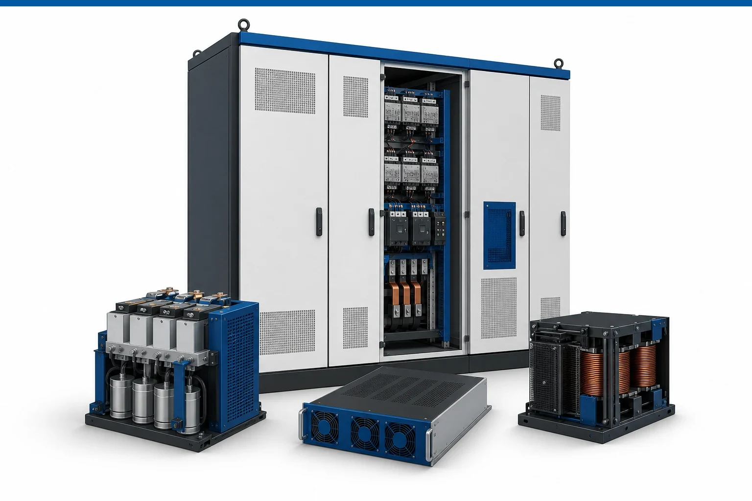
Document cooling, interlocks, and alarm behavior
SVG modules in enclosed switchboards depend on airflow paths that are easy to block during construction. Confirm intake and exhaust clearance, filter service access, and whether ambient sensors match the site class assumed in the layout. If the module includes heater or dehumidifier options, note setpoints and proof-of-operation.
Important: Energizing with blocked ventilation or disabled fans can trip thermal protections and void warranty assumptions (Source: SVG enclosure thermal rating for harsh sites). Resolve cooling defects before load tests, not after the owner reports nuisance trips.
Align protection and CT references with owner acceptance
Protection settings, fuse or breaker coordination, and CT references must match the owner acceptance plan. If the SVG shares CTs with metering or other controllers, document sharing rules and isolation procedures. Partial-load tests should show var command, measured response, and any limiter action without unexplained oscillation.
When projects reference power-factor targets, state whether acceptance uses instantaneous readings, averaged intervals, or a specific load bank scenario. The integrator supplies test sheets; the owner engineer judges compliance against the contract.
Compare integration details with the OEM APF and SVG panel-builder integration guide when APF and SVG modules ship in the same assembly. Shared bus rules, CT placement, and panel space often cross both product lines.
Hand over commissioning records panel builders can defend
The handover package should include as-built redlines, torque logs, insulation or continuity results, no-load and partial-load test sheets, alarm and interlock verification, cooling photos, protection settings, CT sketches, and owner witness signatures where required. List open items with responsible parties instead of informal verbal exceptions.
When the owner or EPC opens an SVG support RFQ, attach the switchboard model context, nominal voltage, module rating, cooling class, communication protocol, test limits already attempted, and photos of any abnormal alarm. Describe whether support needed is field troubleshooting, spare parts, or firmware clarification. CNBYG should not be asked to promise UL listing approval, a guaranteed power-factor result, or a substitute for the owner acceptance test. Submit available records through the CNBYG contact page.

Frequently asked questions
What must be checked before an SVG module is energized?
Verify drawing match, torque marks, grounding and bonding continuity, control wiring polarity, cooling path, CT orientation where applicable, and protection settings against the project record.
Is no-load energization enough for commissioning sign-off?
No. No-load checks confirm boot and alarms, but owner acceptance often requires partial-load or representative operating evidence per the specification.
Who owns the final acceptance decision?
The owner and qualified engineer define acceptance against the project specification. The integrator supplies installation and test documentation.
Should CT polarity be checked only at full load?
No. CT orientation and polarity should be verified during wiring inspection and again when control loops are exercised at partial load.
Can cooling be deferred until the owner complains about temperature?
No. Blocked filters, missing duct paths, or disabled fans should be corrected before load tests because thermal limits affect warranty and service access.
Does this article certify UL listing for a custom switchboard?
No. Listing, labeling, and AHJ acceptance remain the responsibility of the qualified panel builder and project engineer for that assembly.
References
Standards and background sources cited for SVG switchboard commissioning: