So überprüfen Sie die AHF-Leistung gemäß IEEE 519
Verifying AHF performance against IEEE 519 requires measurements at the agreed point of common coupling, suitable instruments, representative operating conditions, and evaluation against the applicable standard requirements. It is not enough to show that a filter reduces one feeder’s instantaneous current THD. Define the installation boundary, distinguish current total demand distortion from current THD, retain individual harmonic results, and record voltage distortion alongside current. An AHF is part of a system solution; its catalogue rating or an alarm-free display does not certify the whole installation. This guide organizes the verification record without reproducing or inventing standard limits.
Agree on the acceptance boundary first
Identify the point of common coupling with the responsible utility or project engineer. Mark it on the single-line diagram and record which installation loads and generation sources it represents. A convenient meter at a downstream machine or filter branch is not automatically an equivalent acceptance point.
Clarify the purpose of the test. A commissioning demonstration of reduced source harmonics, a contractual performance test, and a formal assessment against a standard can require different evidence. State the relevant edition of the standard and any applicable project requirements before collecting data. Do not choose an acceptance method retrospectively because it gives the most favorable result.
Das IEEE 519 Standard-Informationen is the primary starting point for the standard’s scope. Use the authorized standard and qualified engineering review for the actual limits and evaluation rules. This article deliberately avoids a universal percentage table because the applicable current criteria depend on the installation and the required assessment.
Keep equipment selection separate from system verification
Das CNBYG AHF Produktseite identifies the equipment family used for harmonic compensation. Confirm the installed model, current capability, supported topology, settings, and healthy module count against the approved equipment records.
Der separate IEEE 519 and APF sizing guide addresses planning before selection. Here the focus is the measurement and acceptance evidence after installation. A filter selected using reasonable load information can still require commissioning corrections, and a successfully commissioned filter can still face new loads that change the system result.
List other compensation devices and operating arrangements that may influence the test. Include capacitor banks, passive filters, generators, supply transfers, and parallel AHF modules. The final report should explain the configuration being accepted rather than implying that one recording represents every possible plant arrangement.
Understand the current quantities in the report
Current THD uses the fundamental current observed during the measurement as its reference. TDD uses the demand-current reference required by the applicable evaluation. The harmonic numerator and measurement bandwidth also need consistent treatment. Substituting THDi for TDD can produce a misleading conclusion, especially when the plant is lightly loaded.
For a simple arithmetic illustration, suppose the harmonic RMS current is 15 A, the present fundamental current is 50 A, and the agreed demand-current reference is 150 A. The corresponding ratios would be 30 percent THDi and 10 percent TDD under that simplified calculation. These are demonstration values, not measurements from CNBYG equipment or standard acceptance limits.
Document how the demand-current reference was established. Include the data source, period, installation boundary, and responsible approval. Do not choose an unusually large reference simply to reduce the displayed percentage. Where the standard requires particular treatment, follow that requirement and record the basis so another reviewer can reproduce the result.
Prepare an evidence checklist before connecting instruments
| Evidence item | Warum es notwendig ist | Aufzubewahrende Aufzeichnung |
|---|---|---|
| Accepted measurement point | Establishes which installation is evaluated | Marked single-line diagram and agreed PCC |
| Anwendbarer Standard und Anforderungen | Definiert die tatsächlichen Abnahmeregeln | Ausgabe- und Projektbewertungsspezifikation |
| Instrumentenverträglichkeit | Unterstützt das Vertrauen in die erfassten Mengen | Konfiguration, Bereich, Kalibrierung und Methode |
| Laststromreferenz | Unterscheidet TDD von momentaner THD | Stammdaten und Berechnungsgrundlage |
| Einzelne Harmonische Ergebnisse | Verhindert, dass Gesamtverzerrung eine dominierende Ordnung verbirgt | Phasenweise Harmonische Tabellen und Trends |
| Repräsentative Betriebszustände | Setzt das Ergebnis in Bezug zur tatsächlichen Anlagenutzung | Last-, Versorgungs- und Kompensationszustandsprotokoll |
| Nachweis des AHF-Betriebs | Zeigt, welche Geräte verfügbar waren | Modulstatus, Einstellungen und Ereignisprotokolle |
Die Checkliste unterstützt eine reproduzierbare technische Bewertung. Sie zertifiziert nicht selbst die Einhaltung. Elektrische Anschluss- und Messarbeiten müssen von qualifiziertem Personal unter Verwendung entsprechend ausgelegter Instrumente und der genehmigten Sicherheitsverfahren vor Ort geplant werden.
Instrumente für die beabsichtigte Messung auswählen
Bestätigen Sie, dass der Analysator die erforderlichen Strom- und Spannungsgrößen, Harmonische Ordnungen, Aggregationsintervalle und Ereignisinformationen misst. Überprüfen Sie den Bereich der Stromsonde, die Ausrichtung des Leiters, die Phasenzuordnung und die Installations-Topologie vor der Aufzeichnung. Ein Einstellungsfehler kann dazu führen, dass ein präzises Instrument ein irrelevantes Ergebnis liefert.
Das Seite des Messstandards IEC 61000-4-30 identifiziert eine Referenz für Methoden der Netzqualitätsmessung. Die geeignete Instrumentenfähigkeit muss für den Testzweck und die Anforderungen festgelegt werden. Ein Gerät mit einer THD-Anzeige bietet nicht automatisch die erforderlichen Methoden, Aufzeichnungsfunktionen oder Instrumentenklassen.
Bewahren Sie die Konfigurationsdatei und den Kalibrierungsnachweis auf, sofern verfügbar. Erfassen Sie die Identifikation der Sonde und den effektiven Strombereich. Wenn mehrere Instrumente verwendet werden, stimmen Sie deren Uhren und Messkonventionen ab. Kombinieren Sie keine Prozentsätze von Instrumenten mit unterschiedlichen Bandbreiten oder Referenzen, als wären sie direkt vergleichbar.
Aufzeichnung des repräsentativen Anlagenbetriebs
Definieren Sie die Betriebszustände, die vor Beginn der Messung eingeschlossen werden sollen. Berücksichtigen Sie den normalen Produktionsbetrieb, größere nichtlineare Lasten, leicht belastete Perioden und geplante Versorgungskonfigurationen. Die erforderliche Beobachtungsdauer und statistische Auswertung müssen der jeweiligen Bewertungsmethode folgen, anstatt einer festen universellen Minutenanzahl.
Protokollieren Sie Laständerungen und Kompensationszustände zusammen mit der elektrischen Aufzeichnung. Eine günstige Periode, in der ein problematischer Prozess gestoppt wird, spiegelt möglicherweise nicht den normalen Anlagenbetrieb wider. Ebenso sollte ein außergewöhnliches Ereignis identifiziert werden, anstatt es stillschweigend zu entfernen oder ohne Kontext zu verwenden.
Wenn das Projekt einen kontrollierten Vorher-Nachher-Vergleich erlaubt, behalten Sie den gleichen Messpunkt und vergleichbare Lastbedingungen bei. Folgen Sie einem genehmigten Inbetriebnahmeverfahren beim Wechsel des Filterzustands. Einige Anlagen können absichtliches Schalten für eine Demonstration nicht tolerieren; bestehende Betriebsintervalle oder eine andere genehmigte Methode sind möglicherweise geeigneter.
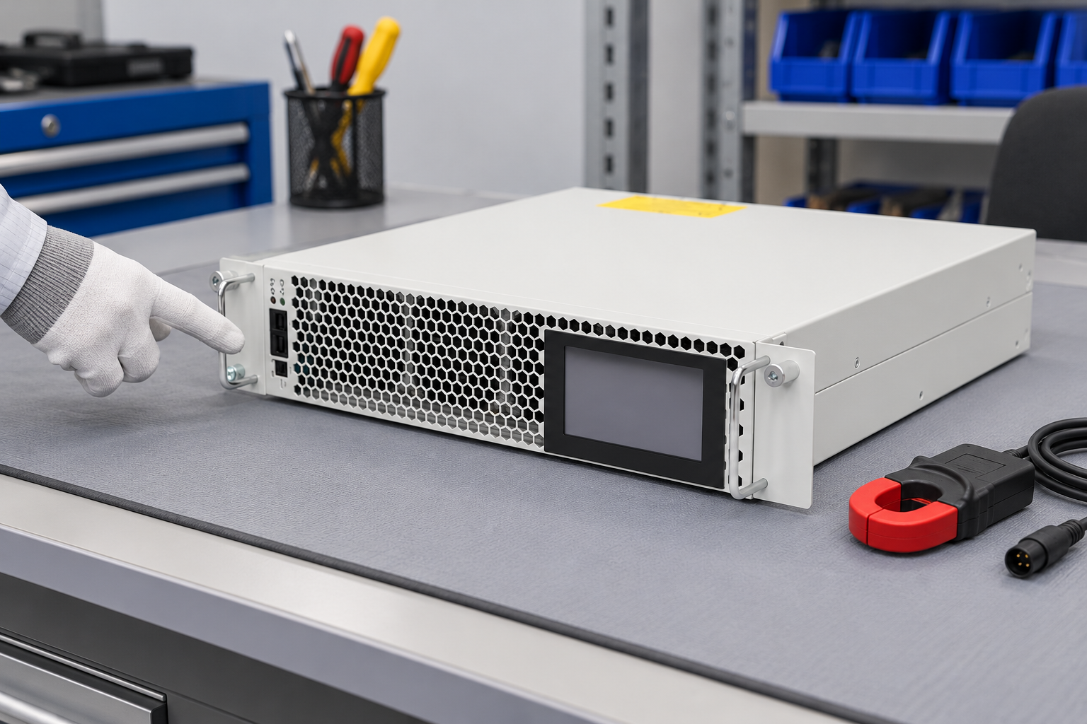
Die Abbildung zeigt ein geschlossenes Referenzprodukt vor der Inspektion. Es ist kein Foto eines Abnahmetests und stellt keine aktuelle Bewertung, Messklasse oder Konformität dar. Der tatsächliche Nachweis erfolgt durch die dokumentierte Installation und aufbewahrte Aufzeichnungen.
Einzelne Harmonische und Spannungswerte auswerten
Bewahren Sie die prophasigen einzelnen harmonischen Ströme und die relevante Gesamtsumme auf. Ein reduzierter Gesamtwert kann mit einer verbleibenden signifikanten Harmonischen Ordnung koexistieren. Überprüfen Sie die entsprechenden Kriterien für jedes Ergebnis, anstatt nur die günstigste Zahl zu berichten.
Evaluate voltage distortion at the accepted boundary as required. Background supply distortion and network impedance can influence voltage results even when the AHF reduces source harmonic current. Do not attribute every remaining voltage component to filter failure without investigating the broader system.
If the result is unsatisfactory, separate a measurement issue, a sensing or configuration issue, a capacity limit, and an upstream condition. The HF-CT-Placeringstipp supports sensing verification. The HFAs Inbetriebnahme-Anleitung supports a controlled installation review before further equipment changes.
Interpret a failure without hiding uncertainty
Record which criterion was not met, the affected phases or harmonic orders, and the operating state. Include the measurement confidence and any missing inputs. If the demand-current reference or PCC remains unresolved, state that the assessment is incomplete rather than declaring a pass or fail using a substitute.
Compare compensation demand with available healthy output. Review module status, protective limiting, current allocation, and the load spectrum. A system may require an installation correction, a settings review, additional capacity, or another mitigation approach. The evidence should explain why that action is justified.
After a correction, repeat the relevant test under comparable conditions and preserve the earlier result. Do not replace the original report with a favorable screenshot. A useful record shows the problem, action, and verified effect, including any remaining operating limitations.
Assemble a report another engineer can reproduce
State the site boundary, standard edition, operating configurations, instruments, demand-reference basis, and evaluation method. Attach the relevant harmonic tables and trends, AHF status, settings, event records, and annotated diagram. Separate observed improvement from the formal acceptance conclusion.
Document the responsible reviewer and the unresolved conditions. If the installation later adds drives, changes supply arrangements, or expands compensation equipment, revisit the measurement plan. Acceptance is tied to the configuration and evidence assessed, not a permanent guarantee for every future load.
The NPTEL IIT Delhi lesson below provides additional educational context for standards and monitoring. It does not replace the applicable standard or a qualified assessment of the site.

Power Quality: Standards und Überwachung
Häufig gestellte Fragen
Does an AHF with a low THDi display comply with IEEE 519?
Diese Anzeige allein ist unzureichend. Die Bewertung erfordert die akzeptierte Systemgrenze, anwendbare Spannungs- und Stromkriterien, einzelne Harmonische Ergebnisse, repräsentative Bedingungen und die erforderliche Messbehandlung. Die Filteranzeige kann auch einen anderen Punkt als den PCC beobachten.
Kann eine Maschinen-Feedermessung eine PCC-Messung ersetzen?
Nehmen Sie keine Gleichwertigkeit an. Der Fütterer kann nur eine Last darstellen und andere Verzerrungsquellen oder Kompensationsgeräte ausschließen. Vereinbaren Sie den Akzeptanzpunkt mit dem verantwortlichen Projekt- oder Versorgungsingenieur und dokumentieren Sie ihn auf dem Installationsdiagramm.
Should the test use THDi or TDD?
Verwenden Sie die Mengen, die durch die geltende Bewertung erforderlich sind. THDi und TDD verwenden unterschiedliche Stromreferenzen und beantworten unterschiedliche Fragen. Bewahren Sie die zugrunde liegenden harmonischen Ströme und dokumentieren Sie die Nachfrage-Referenzbasis, anstatt einen Prozentsatz durch den anderen zu ersetzen.
What should happen after an unsuccessful test?
Die Aufnahmen aufbewahren und das spezifische unerfüllte Kriterium identifizieren. Messung, Sensorik, Konfiguration, gesunde Kapazität und Versorgungsbedingungen überprüfen, bevor eine Korrektur gewählt wird. Die relevante Bewertung unter vergleichbaren Bedingungen nach der gerechtfertigten Änderung wiederholen.