Sättigung des Stromwandlers im aktiven Oberschwingungsfilter: Verzerrte Rückmeldesignale erkennen
Active harmonic filter CT saturation is a measurement problem in which a current transformer no longer reproduces the primary current faithfully under the actual operating condition. Suspect it when the filter’s current feedback becomes increasingly inconsistent with a suitable independent measurement as load changes, but do not diagnose it from high THD or a flattened waveform alone. First verify CT identity, ratio, polarity, phase mapping, measurement location, secondary burden, and instrument bandwidth. Establish whether distortion belongs to the primary load current, the CT, or another part of the measurement chain before changing filter capacity or settings.
Why distorted feedback matters
An AHF uses current information as part of its compensation process. If the measurement path misrepresents the current, an apparently reasonable setting can operate on misleading evidence. The observed result may resemble an undersized filter, an incorrect ratio, an unsuitable control boundary, or a changing load. Those possibilities require different remedies. Replacing the filter or adjusting compensation priorities before checking the feedback can leave the initiating problem unresolved.
This guide focuses on the distinction between CT saturation and other feedback errors. It complements the AHF CT ratio investigation und der Anleitung zur CT-Platzierung und Verkabelung. It does not provide a universal saturation threshold, approve a particular CT replacement, or authorize testing an energized secondary circuit by disconnecting it.
Establish which measurement path is installed
Record the actual AHF model, the specified sensing arrangement, CT identification, selected tap where applicable, primary and secondary ratings, input compatibility, and the approved installation drawing. Confirm whether the system uses conventional current-output CTs or another documented sensor arrangement. Procedures suitable for one sensor type must not be transferred to another simply because both measure current.
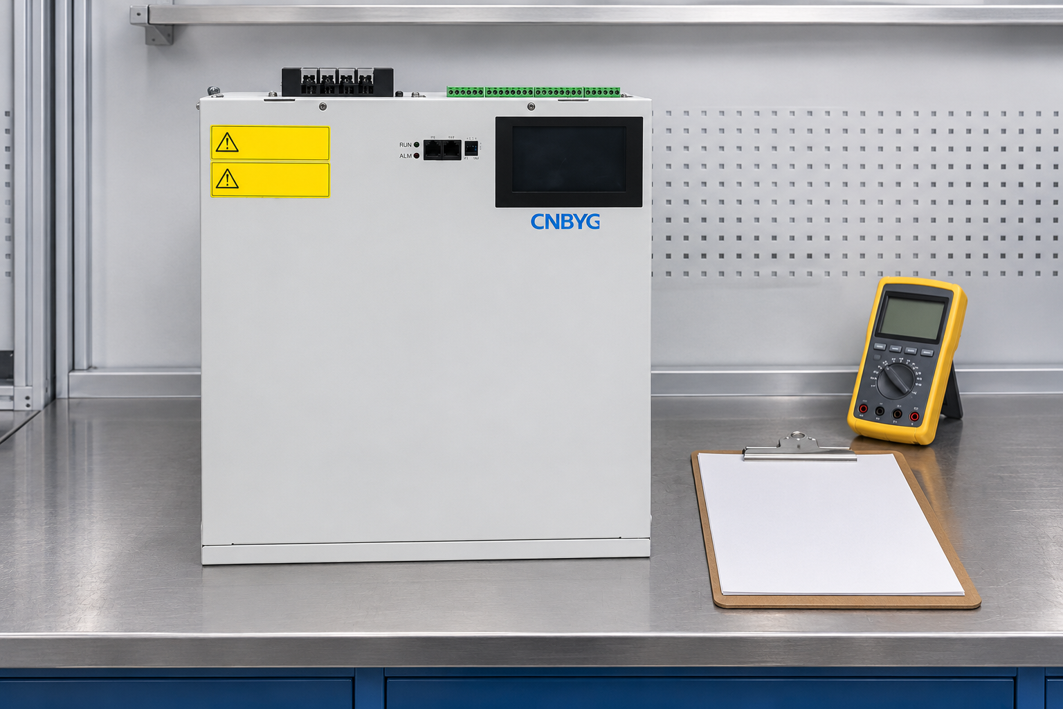
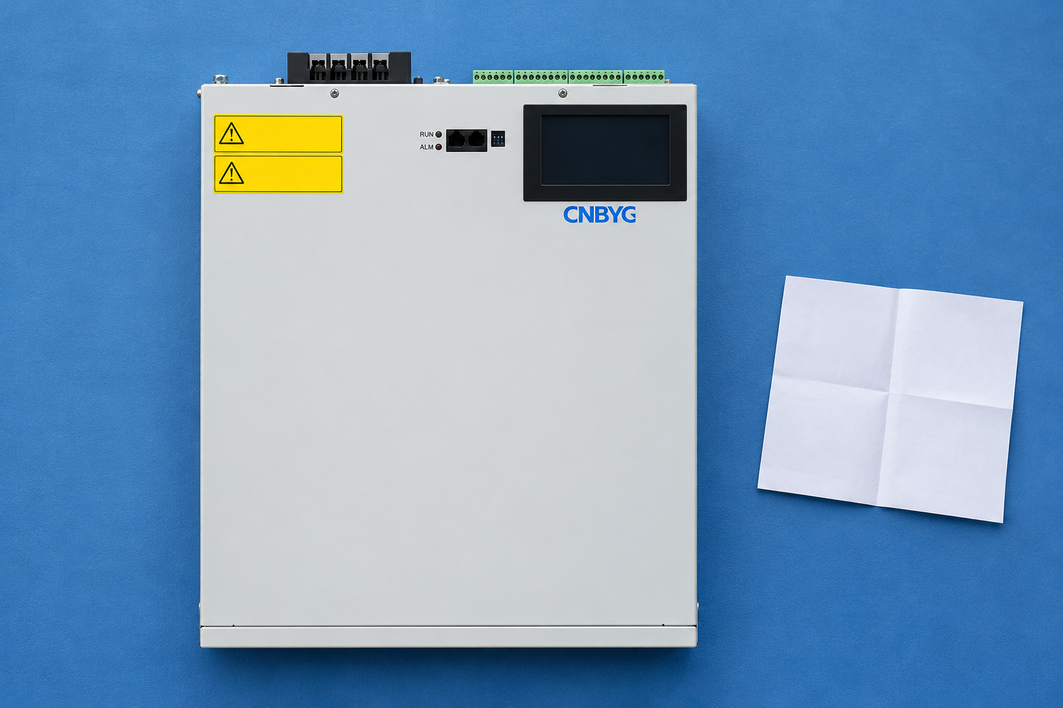
Benutzen Sie CNBYG active harmonic filter product information and the delivered manual to establish the applicable equipment boundary. This article does not claim that every CNBYG variant uses an identical input or an internal saturation-detection algorithm. Obtain the specified sensor requirements, permissible secondary loading, and frequency-response information before evaluating substitutes.
Distinguish primary distortion from measurement distortion
Nonlinear loads can draw a distorted primary-current waveform during normal operation. Seeing a nonsinusoidal curve on a display therefore does not prove CT saturation. Compare the installed feedback with a suitable independent measurement of the same primary current and time interval. The reference instrument and sensor must have appropriate range, bandwidth, crest-factor capability, and installation conditions for the comparison to be meaningful.
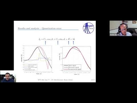
An IPST research paper on CT saturation detection examines distorted secondary signals and reconstruction methods in a protection-system test context. It supports the general point that saturation changes the reproduced signal. Its studied network, algorithms, and numerical results are not specifications for a CNBYG AHF. Do not copy the paper’s test thresholds into a field controller or assume that a protection experiment establishes the behavior of an AHF feedback input.
Use symptoms as hypotheses rather than verdicts
The following table separates fault paths that can look similar on a dashboard. It is a qualitative evidence guide. No row provides an automatic diagnosis, and the absence of a visible symptom does not certify a sensor. Check the installed equipment documentation and the comparison method before assigning a cause.
| Beobachtetes Muster | Mögliche Erklärung | Beweismaterial zum Vergleichen | Avoid the shortcut |
|---|---|---|---|
| Nearly constant proportional difference over several loads | Ratio or scaling mismatch | CT identity, selected tap, configured ratio and simultaneous readings | Changing the ratio to hide a load-dependent error |
| Agreement at one load but increasing divergence at another | CT capability, burden, bandwidth or measurement-chain limit | Comparable waveforms and instrument ranges at both conditions | Declaring saturation from one RMS value |
| Sign or phase relationship is inconsistent | Polarity, mapping or reference mismatch | Approved phase references and the complete signal path | Treating every sign error as saturation |
| Both independent primary measurement and feedback show similar distortion | Actual nonlinear load current | Matched time window, spectrum and sensor suitability | Calling all distorted current a CT fault |
| Feedback clips while the independent reference does not | Sensor or input-chain limitation | CT loading, input range, waveform capture and documentation | Assuming the CT is the only possible limiting component |
| Compensation remains limited with credible feedback | Filter capacity, settings or operating boundary | Output-limit status and measured load conditions | Buying a CT before checking the filter’s actual duty |
cURL Too many subrequests by single Worker invocation. To configure this limit, refer to https://developers.cloudflare.com/workers/wrangler/configuration/#limits
cURL Too many subrequests by single Worker invocation. To configure this limit, refer to https://developers.cloudflare.com/workers/wrangler/configuration/#limits.
Das cURL Too many subrequests by single Worker invocation. To configure this limit, refer to https://developers.cloudflare.com/workers/wrangler/configuration/#limits cURL Too many subrequests by single Worker invocation. To configure this limit, refer to https://developers.cloudflare.com/workers/wrangler/configuration/#limits.
cURL Too many subrequests by single Worker invocation. To configure this limit, refer to https://developers.cloudflare.com/workers/wrangler/configuration/#limits.
cURL Too many subrequests by single Worker invocation. To configure this limit, refer to https://developers.cloudflare.com/workers/wrangler/configuration/#limits
cURL Too many subrequests by single Worker invocation. To configure this limit, refer to https://developers.cloudflare.com/workers/wrangler/configuration/#limits.
cURL Too many subrequests by single Worker invocation. To configure this limit, refer to https://developers.cloudflare.com/workers/wrangler/configuration/#limits.
Plan observations across representative loads
Select operating conditions that are normal and permitted for the installation. Capture a moderate-load condition and the condition associated with the suspected fault where it can be observed safely. Record which loads are running, the AHF operating state, output-limit indications, and the locations of all measurements. Do not create an overload or a fault to provoke CT saturation during a general troubleshooting visit.
Compare simultaneous evidence wherever practical. An independent clamp measurement made before a large drive starts cannot validate a feedback value recorded afterward. For intermittent events, preserve a common time basis or document the uncertainty between instruments. Record the current waveform, the relevant harmonic information, and the load state together. High THD alone is not a universal threshold for CT saturation or thermal failure, and this guide provides no arbitrary percentage at which a CT must fail.
Preserve the CT safety boundary
A conventional current-transformer secondary must not be opened while primary current can flow. Before disturbing a secondary circuit, use the approved isolation, shorting, and test arrangements specified for the installation. Do not unplug sensing leads, insert an unapproved meter in series, or apply an insulation tester across an electronic AHF input as an improvised check. Identify the sensor type before selecting any test method.
OSHA 1910.333 addresses electrical isolation and verification within its scope. Apply the site’s governing electrical safety procedures and use qualified personnel for necessary energized observations. An AHF stop command does not establish that its supply or external sensing circuit is isolated. The primary conductor can remain energized even when the filter itself is not compensating.
Select a remedy from verified evidence
If the investigation confirms an incorrect ratio or phase mapping, correct that documented configuration issue and repeat the comparison. If the connected burden is unsuitable, resolve it through the approved circuit design. If the CT is unsuitable for the measured duty or required frequency response, select a replacement jointly with the AHF and sensor suppliers. Do not increase the CT primary rating merely to make a displayed error disappear without assessing the resulting measurement performance.
Where a signal-chain limit remains uncertain, provide the supplier with the actual captures and configuration rather than adjusting unrelated compensation parameters. A review of AHF compensation performance should distinguish a measurement problem from an output-capacity or network-boundary problem. Keep any operating restriction visible until the approved remedy has been tested.
Verify the complete system after correction
Repeat the relevant measurements with the same locations, instrument settings, and comparable load states. Confirm that the feedback now agrees with the accepted reference within the project’s documented criteria. Then verify the AHF response under the approved commissioning plan. A corrected current indication does not, by itself, establish compliance at the point of common coupling or prove that every harmonic target has been met.
Retain the CT and AHF identities, approved specifications, burden assessment, settings record, before-and-after captures, and final release decision. State what was confirmed and which intermittent conditions remain unobserved. If components or wiring changed, update the approved drawing and the spare-parts information. This prevents a later maintenance substitution from recreating the same mismatch while preserving an apparently familiar ratio setting.
Research background: distorted CT signals
The IPST 2021 presentation linked from the conference’s proceedings accompanies research into CT saturation detection and signal reconstruction. It is included as technical background on why a reproduced current signal can become unreliable. Its protection-system experiment does not establish a built-in AHF function, a field calibration procedure, or an approved software modification for this product.
Häufig gestellte Fragen
Beweist ein hoher THD-Wert, dass ein Stromwandler gesättigt ist?
No. Primary load current can be distorted without CT saturation. Compare the installed feedback with a suitable independent measurement under the same operating condition and investigate the complete measurement chain.
Kann ich die Sättigung durch eine Änderung der Stromwandler-Übersetzungseinstellung kompensieren?
Nein. Eine Anpassung des Übersetzungsverhältnisses stellt keine fehlenden oder verzerrten Wellenforminformationen wieder her. Stellen Sie zunächst fest, ob das Problem auf eine feste Skalierungsabweichung, eine Sensorbegrenzung, die Bürde oder ein anderes Problem in der Signalkette zurückzuführen ist, bevor Sie eine Abhilfemaßnahme auswählen.
Kann derselbe Stromwandler (CT) sowohl für einen AHF als auch für ein anderes Messgerät verwendet werden?
Only if the complete arrangement is explicitly supported by the relevant equipment specifications and approved design. Evaluate input compatibility, wiring, total burden, and safety requirements; do not add a device to an existing secondary circuit by assumption.
Is an AHF stop command enough before disconnecting CT leads?
No. Stopping compensation does not establish isolation of the primary conductor or the sensing circuit. Follow the installation's approved CT safety and electrical isolation procedures before disturbing any connections.