APFC Controller CT Ratio Setup Guide
Set an APFC controller CT ratio from the installed current transformer’s primary and secondary ratings, using the exact input format required by the controller. For an 800/5 A CT, the mathematical ratio is 160:1, but a menu may require “800,” “160” or separate primary and secondary values. These are different conventions. Confirm the manual before entering a number. Correct scaling also depends on a compatible 1 A or 5 A input, CT polarity, measurement phase and installation position. A correct ratio entered into an incorrectly wired circuit will not produce reliable automatic compensation.
This guide explains identification and verification. It is not a live-wiring procedure or a substitute for the diagram supplied with the installed controller. Read automatic power-factor-controller settings for the surrounding setup sequence.
Read both sides of the CT nameplate
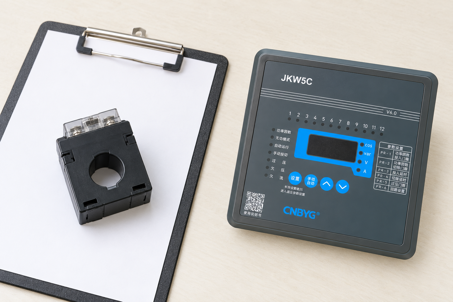
A current-transformer ratio such as 800/5 A describes a nominal primary-current rating and a nominal secondary-current rating. Under ideal proportional operation, a primary current of 400 A corresponds to a secondary current of 2.5 A. The practical measurement also depends on CT accuracy, burden and operating conditions.
Record the complete nameplate, not just the larger number. Check the accuracy designation, rated burden, frequency and any multiple ratios or taps. If a CT has selectable terminals, the connected tap must match the value used in the controller. A photograph of the front label alone may not show which secondary terminals are actually connected.
Do not infer the installed ratio from the switchboard’s breaker rating. The breaker and CT serve different functions and need not have identical primary ratings. When documentation and the physical nameplate disagree, resolve that discrepancy before changing the controller. Preserve the existing setting and drawing as part of the commissioning record.
Know which number the menu expects
Some menus request the primary rating directly because the secondary rating is fixed by the controller input. Other menus request a ratio or separate primary and secondary entries. The terms “CT,” “ratio,” “primary” and “transformation factor” are not used identically by all manufacturers.
For an 800/5 A CT, entering 800 into a field that expects 160 creates a different configuration from entering the correct primary rating into a primary-current field. Similarly, a device expecting a 1 A secondary input must not be configured as if the physical CT were 5 A merely because another panel uses that arrangement.
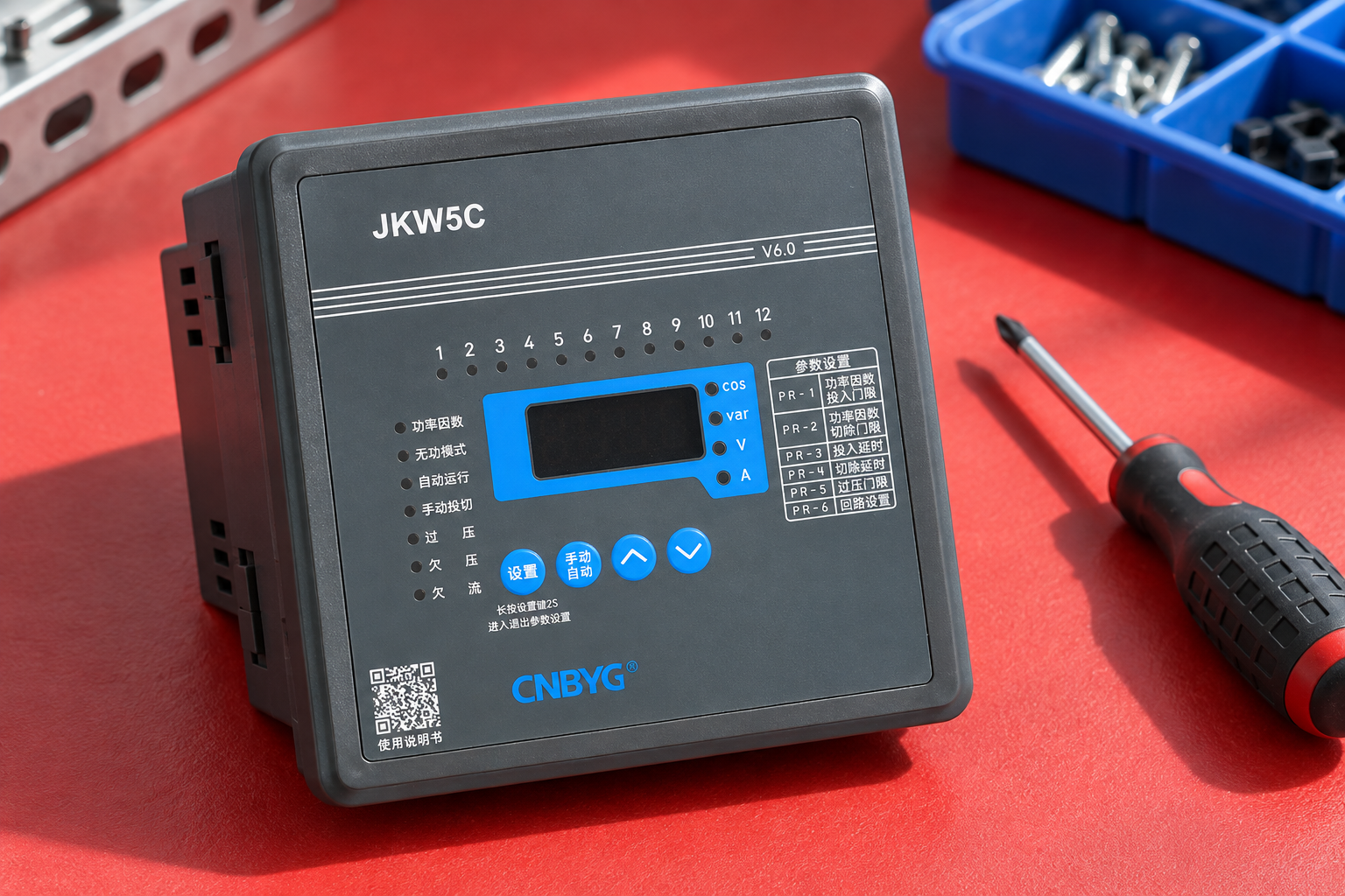
Identify the manual revision and model variant. A display that resembles another controller is not evidence that the setting convention is the same. For CNBYG JKW reactive-power controllers, request the exact model’s setting definition and input rating before commissioning.
Work through a scaling example
Use K = Ip,rated/Is,rated for the mathematical transformation ratio. With an 800/5 A CT, K = 160. If the secondary current measured under an approved method is 3 A, the ideal primary estimate is 480 A. The example illustrates scaling only; it does not authorize opening the circuit or inserting an instrument in an energized CT secondary.
If the controller’s displayed primary current is approximately twice a reliable comparison measurement, investigate the ratio convention, connected tap and meter setup. If the error varies with load, consider the CT’s operating range, burden, accuracy and the instruments’ measurement definitions. A constant multiplier and a load-dependent error suggest different causes.
The controller may use the scaled current for displayed quantities and other functions, while phase relationships determine power-factor calculation. Consequently, changing the ratio is not a universal cure for an incorrect power-factor sign or angle. A ratio error can affect demand or stage detection without explaining every display symptom.
A setup verification table
| Prüfen | Aufzuzeichnende Beweise | Verification question |
|---|---|---|
| Physical CT rating | Primary and secondary nameplate values | Does the connected tap match the documented rating? |
| Controller input | Exact model and current-input rating | Is the physical secondary compatible with the input? |
| Menu convention | Manual page and required units | Does the field expect primary amperes, ratio or two ratings? |
| CT polarity | Approved diagram and terminal identification | Are orientation and secondary polarity correct for the selected scheme? |
| Voltage relationship | Measurement phase and wiring arrangement | Does voltage measurement correspond to the controller’s intended phase relationship? |
| CT position | Single-line drawing and capacitor connection | Can the controller see the load and the correction response? |
| Comparison measurement | Instrument, location, load state and readings | Are equivalent quantities being compared at the same operating state? |
Keep the evidence together. A screenshot of the final menu is useful, but it cannot prove the physical input, polarity or position. The electricity authority’s APFC specification demonstrates that controller measurement and configuration requirements belong to a complete system specification.
CT position determines what the controller sees
In a common centralized arrangement, the CT measures the incoming supply current for the load and compensation connection that the controller is intended to regulate. If the capacitor bank connects outside the measured path, the controller may not see the change created by its own stage commands. The result can resemble a control-setting problem even when the ratio is correct.
A CT on one motor feeder does not necessarily represent the reactive demand of the entire switchboard. Conversely, a supply CT may include several loads with different operating cycles. Confirm the intended regulation point on the single-line diagram, especially where multiple transformers, bus couplers or alternate sources can change the topology.
Do not relocate a CT based on a generic sketch alone. The controller’s supported measurement scheme and actual circuit arrangement must be reviewed by a qualified engineer. Document which source and bus configuration apply to the setup, because a valid arrangement in one switching state may not be valid in another.
Polarity and phase errors require a different correction
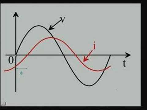
A reversed CT or a mismatched voltage phase can produce an unexpected power-factor sign or phase angle. The exact display behavior depends on the controller’s measurement scheme and sign convention. Do not assume every negative indication means the plant exports active energy or that changing the CT ratio will reverse it correctly.
Use the approved wiring diagram to verify primary orientation, secondary terminal identification and voltage connection. If an automatic phase-detection feature exists, confirm its prerequisites and limitations. An unsuccessful detection routine may reflect insufficient load, an unsuitable connection or a measurement problem, not a defective controller.
For systematic diagnosis, see why an APFC controller shows the wrong power factor. Preserve the original readings and operating state before making an authorized correction. Changing several settings together makes it difficult to determine which error was actually responsible.
The CT secondary must remain safe
An energized CT secondary must not be left open. The California current-transformer rule explicitly addresses this hazard and the use of an appropriate bridged circuit when necessary. Actual work must be performed by qualified personnel under the site’s approved isolation and test procedure.
Do not remove a controller input conductor while primary current is flowing simply to check the nameplate or install another meter. Do not improvise a short with loose tools. Use the designed test or shorting arrangement and the correct work sequence. The safety requirement applies even if the secondary’s normal operating voltage appears low.
Distinguish menu-only changes from physical circuit work. A setting change still needs authorization and a saved configuration, but it does not make the measurement circuit safe to touch. Identify which task is being performed and follow the corresponding procedure.
Verify stage response after ratio configuration
After the physical circuit and setting convention have been confirmed, verify the controller’s behavior through an approved commissioning sequence. Compare measured primary current with a suitable independent instrument at the same location and operating state. Then confirm that a stage command produces the expected reactive response at the regulation point.
Do not force rapid reconnection to accelerate testing. Capacitor discharge and switching-device requirements remain in force. Observe whether the controller recognizes the stage output, whether phase readings are plausible and whether the power-factor indication moves in the expected direction. A working display alone does not establish successful automatic control.
If the controller uses a C/K value, the CT ratio is one of the inputs to its calculation. Refer to APFC C/K calculation and the exact manual. A wrong ratio can distort the threshold or learned stage information even when the displayed power factor seems plausible.
Avoid oversizing the CT without examining low-load operation
A very high primary rating may provide room for growth but can produce a relatively small secondary signal at light load. Verify the controller’s measurement range and the CT’s accuracy under the relevant conditions. A design that works at full production may be less reliable when only a small portion of the plant is running.
Do not select a new ratio solely to make the displayed current look convenient. Consider expected maximum current, minimum operating current, burden, accuracy and physical installation. Any change to the CT should be reflected in drawings, controller configuration and commissioning records.
For stage distribution and light-load resolution, review APFC controller step selection. Measurement quality and available kvar resolution should be designed together, because neither can fully compensate for the other’s limitations.
Record the final configuration
Save the controller model, firmware or manual revision where available, CT nameplate and tap, entered values, menu convention, wiring reference and comparison measurements. Include the date, responsible qualified person and any topology conditions. Record changes individually and preserve the earlier configuration for traceability.
If the result remains uncertain, distinguish verified scaling from unresolved polarity, phase or location issues. Do not label the entire control loop commissioned merely because one current reading matches. A complete record should show how the controller responds to the installed stages under representative operating conditions.
Further learning
Watch Lecture – 15 Power Factor by nptelhrd
The NPTEL power-factor lecture explains the electrical quantities being controlled. Use the installed controller manual for its menu values and measurement connections.
Häufig gestellte Fragen
What is the mathematical ratio of an 800/5 A CT?
It is 160:1. However, the controller menu may ask for the primary rating rather than that mathematical ratio. Confirm the exact input format before entering a value.
Can a wrong CT ratio cause every power-factor error?
No. Scaling, polarity, voltage phase, CT position and measurement definitions can create different symptoms. A ratio change does not correct an incorrectly connected phase relationship.
Can I disconnect the CT wires to check them while the plant runs?
No. An energized CT secondary must not be left open. Qualified personnel must use the approved isolation, bridging or test arrangement and the site’s work procedure.
What proves that the setup is correct?
A verified nameplate and input convention, correct wiring and position, equivalent independent measurements and confirmed stage response at the intended regulation point provide the required evidence together.