


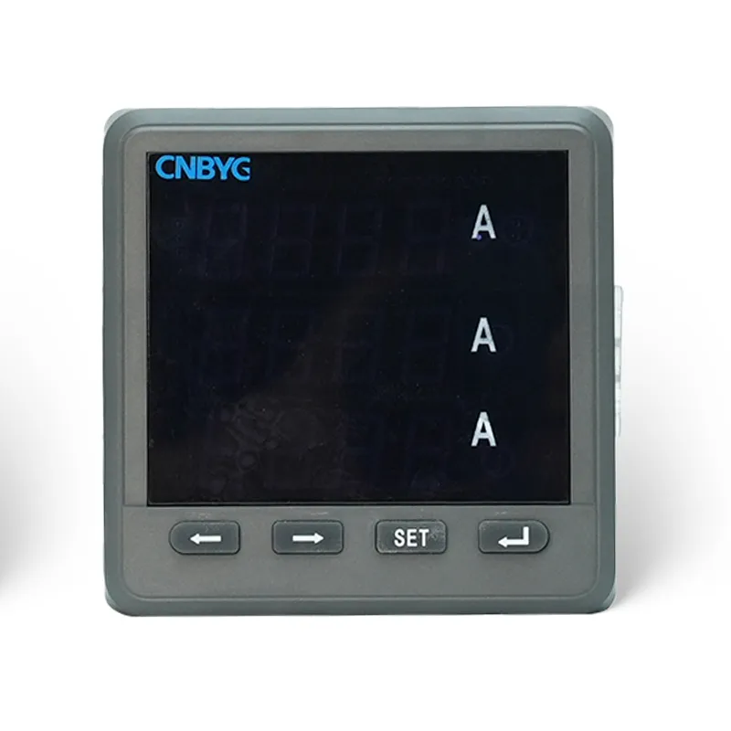
Multifunction power meter wiring begins with the approved meter diagram, system topology, and transformer ratios—not with terminal labels viewed in isolation. Confirm whether the circuit is single-phase, three-phase three-wire, or three-phase four-wire; identify direct-voltage or potential-transformer inputs; match each current transformer to the same phase voltage; observe CT polarity; and provide correctly rated protection and shorting facilities. After energization, validate phase sequence, voltage, current, active and reactive power, power factor, energy direction, and communications against an independent reference. The checklist below helps qualified technicians commission an industrial panel meter without turning a wiring mistake into a software correction or an unsafe live-work task.
- Start with the measurement architecture
- Plan isolation, protection, and CT safety
- Match voltage phases and current channels
- Enter transformer ratios and wiring mode
- Commission measurements in a controlled sequence
- Validate communications without compromising metering
- Diagnose impossible readings
- Create a commissioning record
- Perform a reasonableness review before handover
- Entscheidungstabelle
- Quellen und weiterführende Literatur
- Häufig gestellte Fragen
Start with the measurement architecture
A multifunction meter calculates rather than merely displays. Its kW, kvar, power factor, demand, energy, imbalance, and harmonic values depend on correct voltage and current vectors. Before wiring, mark the measurement point on the single-line diagram and identify the service topology. A three-phase four-wire circuit normally needs three phase voltages plus neutral and three current channels. A three-phase three-wire circuit may use a different voltage and current arrangement defined by the meter. Never infer compatibility from the number of terminals. Confirm the meter's rated input, the PT secondary if used, the CT secondary rating, frequency, and required auxiliary supply from the product documentation.
Plan isolation, protection, and CT safety


Voltage sensing circuits normally require dedicated protective devices sized and coordinated for the conductors and equipment. CT secondary circuits require special care: an energized CT secondary must not be opened because hazardous voltage can develop. Use approved shorting blocks or test switches and follow the site's switching procedure. Keep measurement conductors organized, identified at both ends, and separated from noisy power or control wiring where the design requires it. De-energize before installation and verify absence of voltage with suitable test equipment. OSHA 1910.333 provides the baseline rule for de-energizing live parts before work unless a stated exception is met.
Match voltage phases and current channels
Label source phase A, B, and C consistently from the measurement point through fuses, terminal blocks, and the meter. Route each CT secondary to the current input paired with that phase voltage. Observe the manufacturer's S1/S2 or polarity convention and the CT primary orientation. A crossed phase pair can produce reasonable voltage and current readings while kW, kvar, and power factor are wrong. Before energization, perform continuity and identification checks with the circuit isolated. After energization, compare phase angles or power direction under a known load. If one phase contributes negative power while the others are positive, investigate phase pairing and polarity rather than applying an undocumented software reversal.
Enter transformer ratios and wiring mode
Programming must reflect the installed transformers. Enter CT primary and secondary values and, where applicable, PT primary and secondary values. Confirm whether the meter expects ratios, primary values, or secondary values. Select the exact wiring mode and nominal frequency. A factor-of-five or factor-of-one-thousand error can look like a sensor problem when it is simply a scaling error. Preserve a photo or export of initial settings and record transformer nameplate data. If the meter supports demand intervals, energy pulse constants, or tariff periods, treat those as separate configuration items after basic electrical quantities are proven.
Entscheidungstabelle
| Beobachtetes Symptom | Likely checks | Nützliche Hinweise | Unsafe or misleading response |
|---|---|---|---|
| One phase current is zero | CT circuit, shorting link, terminal and load | Continuity under an approved isolated procedure | Opening an energized CT secondary |
| One phase kW is negative | CT polarity and phase pairing | Per-phase phasor and known load direction | Applying a software sign change without diagnosis |
| All values have the same multiplier error | CT/PT ratios and register scaling | Nameplates, programmed ratios, register documentation | Recalibrating a correctly functioning meter |
| Display is correct but BMS value is wrong | Register, data type, word order and scaling | Side-by-side local and communications readings | Changing the measurement wiring |
| PF or kvar is implausible | Voltage-current phase association | Per-phase angle and independent analyzer | Judging from current magnitude alone |
Commission measurements in a controlled sequence

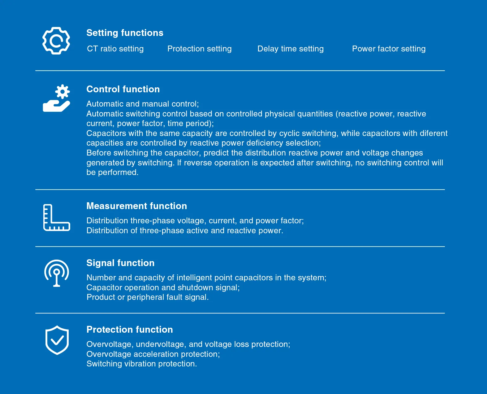
Begin with phase-to-phase and phase-to-neutral voltages as applicable. Confirm phase sequence, then compare each current with a clamp or reference analyzer at the same operating state. Next verify total and per-phase kW, kvar, apparent power, and power factor. Finally check accumulated energy direction and demand. Use a stable load long enough to distinguish real variation from instrument disagreement. Record instrument models, calibration status, connection point, time, and load state. Agreement should be judged using the accuracy classes and uncertainty of the complete measurement chains; a display with more decimal places is not automatically more accurate.
Validate communications without compromising metering
For Modbus or another fieldbus, verify physical layer, address, baud rate, parity, stop bits, register map, and byte order. Use a unique device address and terminate or bias the network according to its design. Read a small set of known values first—such as voltage, frequency, and total active power—and compare them with the local display. A mismatch may come from scaling, signed data types, word order, or a wrong register version. Do not rewire measurement inputs to solve a communications mapping issue. Separate the electrical validation from the data-integration validation so faults remain traceable.
Diagnose impossible readings
Zero current on one phase suggests an open secondary path, shorting link left in place, wrong terminal, or inactive CT. Equal current with one negative phase power suggests reversed CT polarity or crossed phase association. Correct total kW but implausible kvar and power factor often points to phase-reference error. A constant multiplier error suggests CT or PT scaling. Fluctuating communications with a stable display points to network settings or wiring rather than the voltage and current inputs. Use a symptom-evidence-correction log and change one verified cause at a time.
Create a commissioning record
cURL Too many subrequests by single Worker invocation. To configure this limit, refer to https://developers.cloudflare.com/workers/wrangler/configuration/#limits.
Perform a reasonableness review before handover
cURL Too many subrequests by single Worker invocation. To configure this limit, refer to https://developers.cloudflare.com/workers/wrangler/configuration/#limits.
Wie dieses Thema mit CNBYG-Geräten zusammenhängt
Dieser Leitfaden unterstützt Spezifikations- und Inbetriebnahmegespräche für die cURL Too many subrequests by single Worker invocation. To configure this limit, refer to https://developers.cloudflare.com/workers/wrangler/configuration/#limits Produktpalette. Die Produktdaten müssen auf die tatsächliche Systemspannung, den Lastprofil, die harmonischen Messungen, die Schutzkonzepte, die Umweltbedingungen und die geltenden Projektanforderungen überprüft werden. Teilen Sie ein Einzelliniendiagramm und repräsentative Messwerte, bevor Sie eine Modellempfehlung anfordern.
Verwandte CNBYG-Technikleitlinien
- cURL Too many subrequests by single Worker invocation. To configure this limit, refer to https://developers.cloudflare.com/workers/wrangler/configuration/#limits
- cURL Too many subrequests by single Worker invocation. To configure this limit, refer to https://developers.cloudflare.com/workers/wrangler/configuration/#limits
- cURL Too many subrequests by single Worker invocation. To configure this limit, refer to https://developers.cloudflare.com/workers/wrangler/configuration/#limits
Quellen und weiterführende Literatur
Das Handbuch für motorische Systeme des US-Energieministeriums Erklärt, wo die Fest- und automatische Leistungsfaktorkorrektur in die industriellen Lastmuster passt. OSHA 1910.333 bietet den USA eine Referenz für die Praktiken bei der Entenergierung und der elektrischen Arbeiten. IEEE 519 ist die Referenz für die harmonische Regelung an der Schnittstelle zur gemeinsamen Kopplung. Anwenden Sie die aktuellen Ausgaben und die lokalen Anforderungen für das Projekt.

Weiterführender Lernbedarf: MIT OpenCourseWare-Vorlesung 4: Leistungsfaktor. Die MIT-Vorlesung erklärt den Leistungsfaktor und die Verzerrung; sie ersetzt keine spezifischen Geräteanweisungen für Projekte.
Häufig gestellte Fragen
cURL Too many subrequests by single Worker invocation. To configure this limit, refer to https://developers.cloudflare.com/workers/wrangler/configuration/#limits
Nein. Dreiphasen- Dreileiter- und Vierleiter-Systeme können unterschiedliche Eingangsanordnungen erfordern. Folgen Sie dem genauen Zählerschema für die installierte Topologie.
Warum darf eine Sekundärwicklung eines Stromwandlers nicht offen gelassen werden?
Ein stromdurchflossener Stromwandler kann gefährliche Sekundärspannungen entwickeln, wenn sein Stromkreis geöffnet wird. Verwenden Sie zugelassene Kurzschluss- und Isolationsverfahren.
Why are voltage and current correct but power factor wrong?
Der Stromkanal kann mit der falschen Spannungsphase gekoppelt sein, die CT-Polung kann umgekehrt sein oder der Verkabelungsmodus kann falsch sein.
Was sollte vor dem Anschluss eines BMS überprüft werden?
Zuerst lokale elektrische Messwerte validieren, dann Adresse, Seriell-Einstellungen, Registerkarte, Datentypen, Wortreihenfolge und Skalierung bestätigen.
Endgültige technische Hinweise: Behandeln Sie Formeln und Checklisten als Screening-Tools. Installation, Schutz, Inbetriebnahme und energiegeladene Prüfungen müssen von qualifiziertem Personal unter Verwendung von genehmigten Zeichnungen, Produkthandbüchern, Studien und Sicherheitsverfahren vor Ort durchgeführt werden.
Für den zugehörigen Messarbeitsablauf siehe unseren Leitfaden zu cURL Too many subrequests by single Worker invocation. To configure this limit, refer to https://developers.cloudflare.com/workers/wrangler/configuration/#limits.