


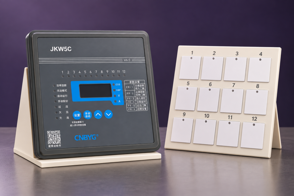
Choose an APFC controller’s number of steps from the capacitor stages that actually need independent control, their kvar ratios and the plant’s load variation. More outputs do not automatically produce better correction. A controller with many outputs can still perform poorly if the smallest stage is too large, the CT sees the wrong part of the system or the programmed stage sequence does not match the installed bank. Define the required compensation range and resolution first, then confirm output compatibility, switching behavior and the manufacturer’s supported control algorithm.
This guide helps industrial panel builders specify a controller without confusing output count with bank capacity. For the wider commissioning context, see automatic power-factor-controller settings.
Separate controller outputs, capacitor stages and units
A controller output commands a switching function. A capacitor stage is an independently switched branch. A stage may contain more than one capacitor unit, depending on the design. These quantities should not be used interchangeably. Twelve physical capacitor cans, for example, do not necessarily require twelve controller outputs if several cans belong to one switched stage.
Confirm whether the bank uses contactors, thyristor switching or another approved arrangement. The controller output type must be compatible with the switching interface. An unused relay output is not automatically interchangeable with a static-switch command. Read the exact controller and switching-device documentation before assigning outputs.
Also check whether some outputs are reserved for alarms, fan control or other functions. A headline “twelve-output controller” may not describe twelve available capacitor-stage commands under every configuration. The RFQ should state the required independent compensation stages and any separate auxiliary functions.
Estimate compensation demand before selecting steps
The familiar fundamental-frequency sizing relationship is Qc = P × (tan φ1 − tan φ2), with cos φ1 and cos φ2 representing the initial and target displacement power factors. This estimates a compensation requirement for a defined operating condition; it does not automatically determine stage count. Collect several operating points, including light load, typical production and peak reactive demand.
A single peak-demand calculation can lead to a bank that has sufficient total capacity but poor light-load control. If the smallest stage supplies more kvar than the load needs, the controller may alternate between lagging and leading conditions. Increasing output count while keeping the same oversized minimum stage does not solve that limitation.
Use the actual load profile rather than an average power-factor number from a bill alone. The controller responds to changing measurements at its CT location, and the utility may evaluate a different interval or power-factor definition. See calculating kvar from kW and power factor for the arithmetic inputs and their limitations.
Minimum stage size determines useful resolution
Useful resolution is the change in reactive output the bank can actually deliver. The smallest stage and the permitted stage combinations determine that resolution. Several identical large stages provide capacity but may still leave a broad gap between available correction states.
Consider an illustrative requirement that varies between 10 and 100 kvar. Five 20 kvar stages provide 100 kvar total capacity, but cannot deliver a standalone 10 kvar state. A design containing an appropriately selected smaller stage can offer finer control. This example explains the tradeoff; it is not a complete bank design, because harmonic duty, switching devices, voltage and protection still need evaluation.
Some banks use equal stages, while others use weighted combinations. Confirm that the controller supports the actual ratios and that its algorithm can select the intended combinations. A programmed ratio list that does not match physical stage output can mislead the controller even when every output and contactor works.
Use a controller-selection checklist
| Selection question | Information to verify | Consequence if ignored |
|---|---|---|
| How many branches need independent control? | Actual stage drawing and output allocation | Outputs may be insufficient or unnecessarily specified |
| What is the smallest stage output? | Net kvar at operating voltage | Light-load correction may be too coarse |
| Are stages equal or weighted? | Installed kvar ratios and supported algorithm | Selected combinations may not match the control model |
| Which switching technology is used? | Relay, static-command or approved interface details | The controller may be incompatible with the switching device |
| What load changes must be followed? | Production profile and response requirement | A slow bank may not follow demand, while excessive switching increases wear |
| Where does the CT measure? | Single-line diagram and capacitor connection point | The controller may fail to see the result of correction |
| Which auxiliary functions are needed? | Alarm, cooling and communication requirements | Available stage outputs may be fewer than expected |
This is a design checklist, not a ranking of controller brands. The Egyptian electricity authority’s APFC specification illustrates how control, protection and setting requirements are specified together. Confirm the exact features of the chosen controller rather than assuming all APFC devices implement them identically.
Avoid choosing stages solely from total kvar
Total bank output addresses the upper end of compensation demand. It does not describe the lower end, switching frequency or combinations available between them. Select both total capacity and the distribution of stage sizes. Verify the net output of detuned branches rather than adding standalone capacitor nameplate values without the reactor relationship.
Allow for the equipment’s operating environment. Voltage variation changes capacitor output, and deterioration can change actual stage capacity over time. A controller that learns stage output may assist operation, but learning does not make an unsuitable bank design appropriate. The manufacturer’s supported learning method and minimum signal conditions should be understood.
If the plant has distortion-driven low total power factor, additional capacitor stages may not solve the underlying issue. Distinguish displacement correction from harmonic mitigation before expanding the bank. Use the measured harmonic study and the appropriate equipment selection rather than using output count as a proxy for power-quality performance.

Consider the control sequence and switching duty
Linear, circular and optimized stage-selection methods have different objectives. Some sequences follow a fixed order; others distribute operating duty or choose combinations that better match demand. The available implementation is model-specific. Do not assume that a label in one manual corresponds to the same algorithm in another.
A circular strategy may distribute switching duty among equivalent stages, but it does not create smaller kvar increments. Unequal stages require the algorithm to account for their sizes. Check whether individual stage lockouts, minimum connection times or switching priorities affect which combinations remain available.
The required response time should match the load, capacitor discharge requirements and switching-device duty. Mechanical contactor banks should not be configured as if they were fast thyristor systems. For the physical stage-sizing decision, use capacitor-bank step-size selection alongside this controller-output assessment.
CT configuration is part of step selection
The CT ratio, measurement input and installation position influence the controller’s ability to identify reactive demand and stage response. A controller with fine stage resolution can still fail to control properly when the signal is too small, scaled incorrectly or measured on an unsuitable feeder.
Confirm the CT primary and secondary ratings, supported controller input and the actual wiring diagram. Do not assume a 1 A and 5 A input are interchangeable. Never open an energized CT secondary while changing the measurement circuit. The California current-transformer safety rule is a reference for this hazard; qualified personnel must follow the site’s approved procedure.
If the controller requires a C/K threshold or stage-learning setup, use the actual smallest stage and the manufacturer’s definition. A generic setting copied from another bank can undermine the benefit of a carefully selected stage distribution. Record the installed configuration so later replacements do not silently change it.
Specify practical expansion without speculative oversizing
If expansion is genuinely planned, document the expected additional stages, kvar distribution and timing. Reserve outputs only where they serve a defined future configuration. More outputs can provide flexibility, but they do not replace cabinet space, busbar capability, ventilation, protection or a revised harmonic assessment.
Check whether future stages would require different switching technology or output interfaces. An extra relay count is not enough if the later load requires a fast response system. Also assess whether the CT, controller range and original minimum stage remain suitable after the plant expands.
Keep unused outputs disabled until their stages are installed and commissioned. Do not program phantom stages into the active sequence merely to fill the controller’s available channels. Document the difference between installed capacity and reserved capacity in the panel record.
Commission the actual stage allocation
Before automatic operation, compare every output number with the physical stage drawing. Confirm switching-device identity, stage output, protective components and any reactor matching. Use the approved commissioning method to verify that each commanded stage produces the intended response and that the controller’s measurement reflects the change.
Record disabled stages and their reasons. A bank that appears to reach target power factor during one test may still lack required capacity if a stage remains unavailable. Repeat the assessment under representative load conditions and include light-load behavior. Check for repeated switching or overcompensation instead of judging success only at peak demand.
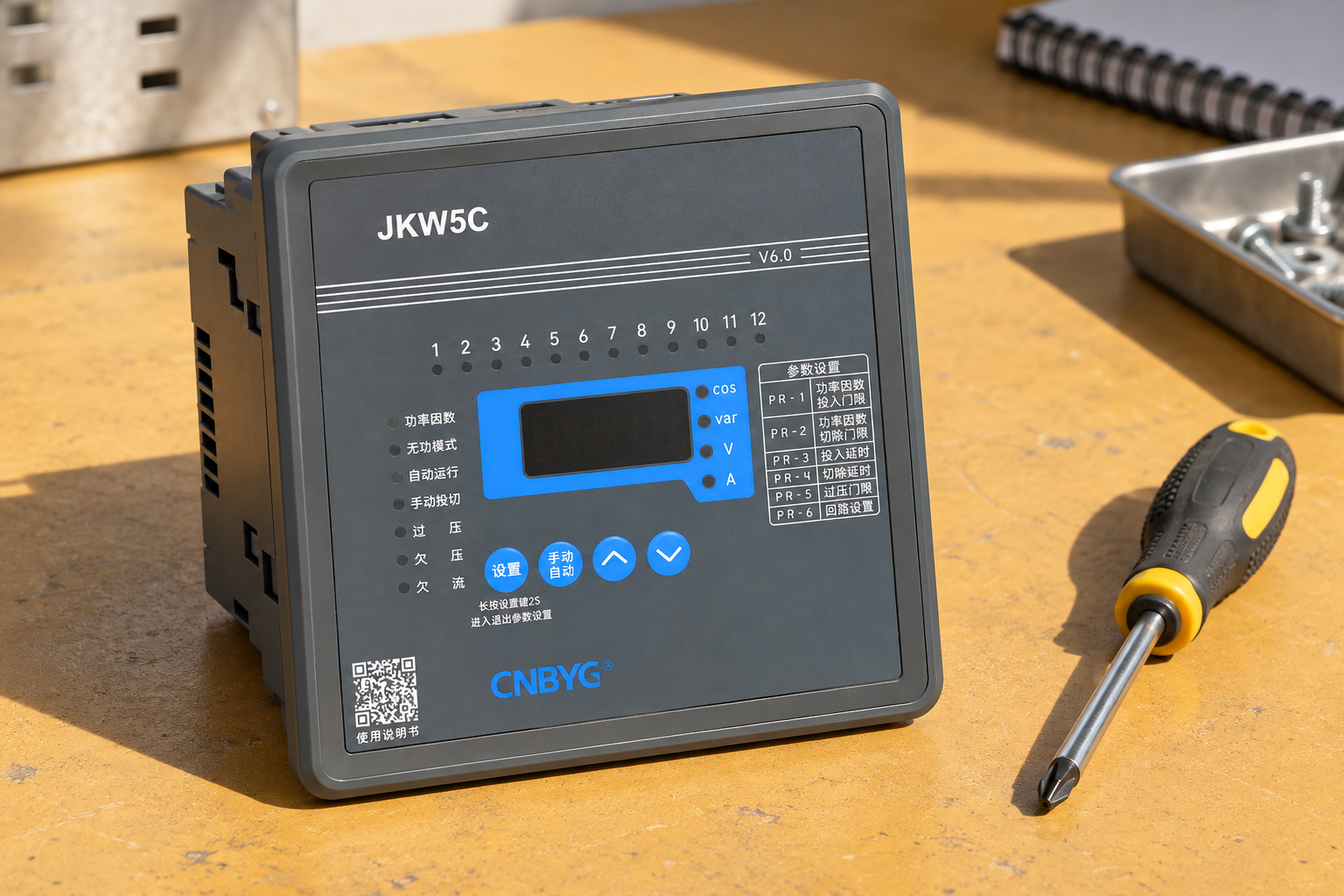
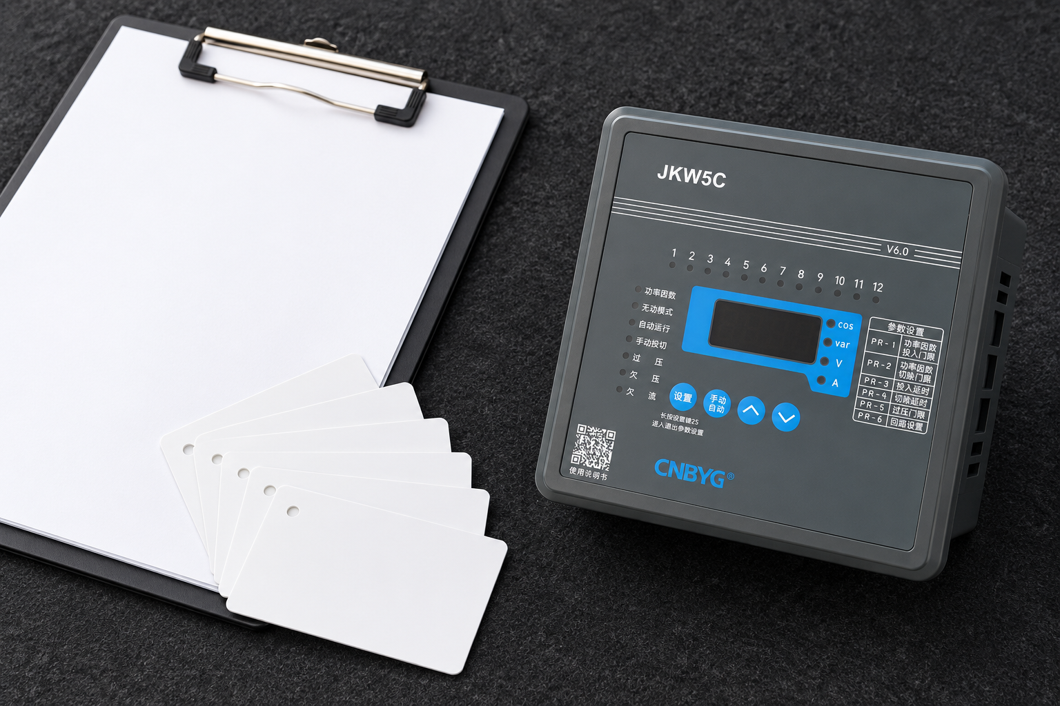
For CNBYG JKW reactive-power controllers, provide the stage drawing, kvar sequence, CT details, switching interface and load profile. Confirm the exact model’s supported functions and outputs. This article does not infer that every product in the series has identical features.
Further learning

Watch Lecture – 15 Power Factor by nptelhrd
The NPTEL power-factor lecture explains the electrical objective of reactive compensation. It complements stage selection; it is not a programming manual for the installed controller.
Preguntas frecuentes
Does a twelve-step controller need twelve capacitor stages?
No. Configure the installed stages and disable unused outputs according to the manual. Confirm whether any outputs are allocated to auxiliary functions and whether the chosen control algorithm supports the actual stage sizes.
Will more steps always improve power factor?
No. Improvement depends on useful kvar resolution, total capacity, CT measurement, switching behavior and load conditions. More outputs cannot compensate for an oversized minimum stage or incorrect configuration.
Can unequal stages be used with any APFC controller?
Only if the specific controller supports the intended ratios and selection method. Verify the actual manual and commission the physical stage sequence rather than assuming generic compatibility.
What should be included in a controller quotation request?
Provide independent stage count, installed kvar ratios, operating voltage, CT ratings and location, switching interface, load profile and required auxiliary functions. Identify real expansion requirements separately.