


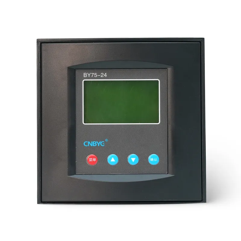
An automatic capacitor bank measures a facility’s reactive demand and switches capacitor steps in or out to keep displacement power factor within a target band. Its controller uses voltage and CT signals, delay and deadband settings, step availability, and discharge rules to decide when to operate contactors, thyristor switches, or compound switches. Correct operation depends on proper sensing, step sizing, switching duty, harmonic assessment, protection, ventilation, and commissioning; the controller cannot repair a wrong CT direction, failed step, or resonance-prone design.

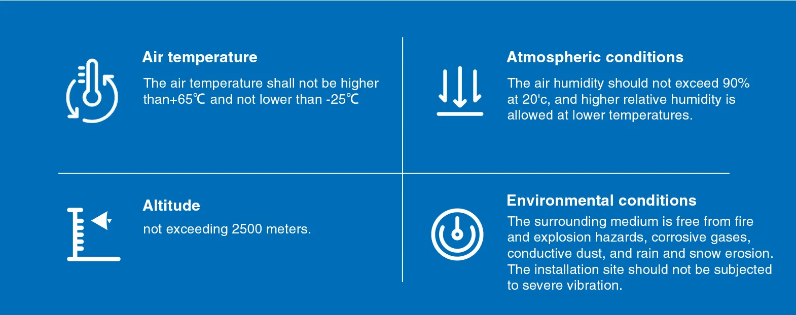
Automatic Capacitor Bank Operating Cycle
The controller reads voltage and current through its sensing inputs, calculates displacement power factor or reactive power, compares the result with the target and deadband, and decides whether a step should be added or removed. It then waits for the programmed delay, checks blocking conditions, commands an eligible switching device, and verifies the new condition. The cycle repeats as load changes. A good controller does not chase every short transient. It uses delay, deadband, step logic, and discharge rules to prevent rapid switching while keeping reactive demand inside the required operating range.
Main Components
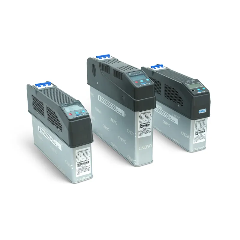
A complete automatic bank includes capacitor steps, branch protection, busbars, a power-factor controller, CT input, voltage reference, contactors or thyristor/compound switches, discharge devices, ventilation, enclosure, and often reactors where the harmonic study requires detuning. The controller is only the decision layer; it cannot compensate if the CT is installed incorrectly, a step fuse is open, a contactor is welded, or the capacitors have lost capacitance. Ratings must cover system voltage, kvar, switching duty, temperature, fault current, harmonics, and the owner’s standards.
How the Controller Determines Direction
Inductive loads normally require leading capacitive vars, so the controller adds steps when lagging reactive demand exceeds the target band. If compensation becomes excessive and the site turns leading, it removes steps. Sign conventions vary among meters and controllers, so commissioning must prove the CT direction, voltage phase reference, and import/export convention. A negative value does not universally mean leading or lagging. Test with a known load and observe whether adding one step moves the measured kvar and power factor in the intended direction before enabling automatic operation.
Step Selection Logic
Banks may use equal steps, binary ratios, or mixed sizes. Equal steps are easy to maintain; graduated steps offer finer control across a wide load range. Controllers can use first-in-first-out rotation, best-fit selection, circular switching, or fixed priority. Rotation distributes wear, while best-fit logic can reduce residual kvar. The algorithm must know actual step size and availability. If a step has failed or been isolated, leaving it marked available can cause repeated commands and poor control. Commission actual kvar response rather than assuming every installed step still matches its nameplate.
| Control item | Propósito | Bad result if wrong |
|---|---|---|
| Target and deadband | Define acceptable reactive range | Leading operation or hunting |
| Delay | Reject short load changes | Excess switching or slow correction |
| Step size data | Select useful kvar increment | Repeated commands and residual kvar |
| Discharge lockout | Prevent charged-step reconnection | Severe transient current |
| Rotation | Share operating wear | One step ages prematurely |
Delay, Deadband, and Hunting
The target power factor defines the desired region; deadband prevents switching for small measurement movement; delay requires the condition to persist before action. Settings that are too tight cause hunting, contact wear, and unnecessary voltage changes. Settings that are too slow leave avoidable reactive demand during stable loads. Match them to process behavior, tariff interval, switching-device endurance, capacitor discharge time, and interaction with generators, UPS systems, solar inverters, SVGs, or other banks. Motor starting and welding bursts should not automatically trigger a large capacitor step that remains after the event ends.
Switching Devices
Capacitor-duty contactors use early-make contacts and damping resistors to limit inrush before the main contacts close. Thyristor switches provide rapid, contactless switching for fast-changing loads but produce losses and require thermal management. Compound switches combine electronic transition with a mechanical path in some LV systems. Ordinary motor contactors should not be selected only from ampere rating because capacitor energization is a different duty. Verify applicable utilization category, kvar rating at system voltage, inrush capability, operating frequency, and coordination with fuses and discharge devices.

Discharge and Reconnection
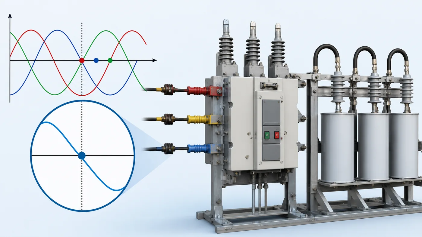
A disconnected capacitor retains charge until its discharge path reduces voltage. Reconnecting a charged step out of phase can create severe transient current. The controller and switching design must enforce the required discharge or residual-voltage condition before re-energization. Confirm discharge resistors are present, correctly connected, and suitable for the switching cycle. Fast-switching systems use equipment designed for that duty rather than bypassing a safe delay. After loss of control power, the restart sequence should not energize multiple steps before measurements and discharge conditions are valid.
Harmonics and Detuned Banks
Variable-frequency drives, rectifiers, UPS systems, welders, and other nonlinear loads produce harmonic current. A plain capacitor bank can resonate with system inductance and amplify distortion or overheat capacitors. Measure the spectrum and perform an impedance assessment before selecting a detuned bank or filter. Series reactors shift the resonance below a targeted harmonic region and limit some inrush, but reactor percentage, capacitor voltage, current, and thermal duty must be engineered together. An automatic controller does not detect every resonance risk simply because the displayed fundamental power factor looks good.
Sizing Total kVAR and Steps
Estimate total kvar from measured real power and present versus target displacement power factor, then validate across minimum and maximum load. Total rating covers the largest stable reactive requirement; smallest step controls resolution. Avoid a first step larger than the persistent minimum demand, which can create leading operation at light load. Consider transformer magnetizing vars, motor operating states, generation, and future expansion. The dedicated sizing guide provides the formula; this working-principle page focuses on how the automatic system applies those steps after the engineering values are selected.
CT Placement and Common Errors
Place the controller CT where it measures both the load and the effect of the capacitor bank, using the phase and polarity required by the controller. If the CT measures only the load, the controller may keep adding steps because it cannot see compensation. If capacitor current passes in the wrong direction relative to load current, the displayed response can reverse. Other errors include wrong CT ratio, mismatched voltage phase, loose secondary wiring, parallel conductors not fully enclosed, and grounding practices that violate the manufacturer instructions. Verify with primary load changes and one-step tests.
Commissioning Sequence
Inspect ratings, clearances, torque, grounding, fuses, reactors, ventilation, switching devices, discharge components, and CT wiring. With automatic mode disabled, confirm voltage and current values and lead/lag direction. Switch each step manually, measure kvar and current, check abnormal sound or heating, and record its actual response. Verify discharge/reclose blocking, alarms, failed-step logic, fan operation, and emergency stop. Then enter target, deadband, delay, step sizes, and rotation logic. Observe several stable load changes before leaving the bank in automatic service.
Maintenance and Troubleshooting
Trend power factor, kvar, step status, switching counts, capacitor current, temperature, voltage, harmonics, alarms, and controller commands. A low power factor with all steps commanded may indicate blown fuses, failed switching devices, lost capacitance, incorrect sensing, insufficient installed kvar, or harmonic blocking. Repeated step changes suggest hunting, process cycling, wrong step data, or interaction with another controller. Bulging, leakage, odor, hot connections, noisy reactors, or repeated fuse operation require isolation and investigation. De-energize, discharge, test, and ground according to the approved safety procedure before touching components.
RFQ Checklist
Provide system voltage and frequency, transformer and fault level, measured kW/kvar/power-factor profile, target and tariff rule, minimum load, total kvar, step sequence, switching frequency, CT ratio and location, harmonic spectrum, reactor requirement, ambient and enclosure conditions, communication, alarms, protection coordination, and applicable standards. Ask suppliers to state capacitor, reactor, contactor or thyristor ratings at the actual system voltage; controller logic; discharge method; ventilation losses; fault withstand; test records; and spare parts. Use CNBYG reactive-power products only after these project inputs are confirmed.
Change Control and Operating Records
Treat controller settings as controlled engineering data. Record the approved target, deadband, delays, CT ratio, step sequence, unavailable steps, firmware version, and commissioning measurements. When a process, transformer, generator, solar system, or major nonlinear load changes, compare new trends with the baseline before altering settings. A written record prevents operators from repeatedly tightening the target to hide a failed step, and it makes later troubleshooting faster because measured behavior can be compared with a known healthy condition.
Related Guides
Continue with controller settings, kvar sizing, capacitor contactors, y detuning reactors.
Preguntas frecuentes
How does an automatic capacitor bank work?
It measures reactive demand and switches capacitor steps after target, deadband, delay, availability, and discharge checks.
Why does the bank keep switching?
Possible causes include tight settings, rapidly cycling load, incorrect CT wiring, wrong step data, or interaction with another controller.
Can a normal contactor be used?
Use switching equipment rated for capacitor duty and the actual kvar, voltage, inrush, and operating frequency.
Does automatic correction remove harmonics?
No. Fundamental reactive compensation and harmonic mitigation are separate design questions.
Why is the CT location important?
The controller must measure both load demand and the change produced by its capacitor steps.
Referencias
- IEEE 1036 — Aplicación de condensadores de potencia en derivación
- U.S. DOE — Reducing Power Factor Cost
