


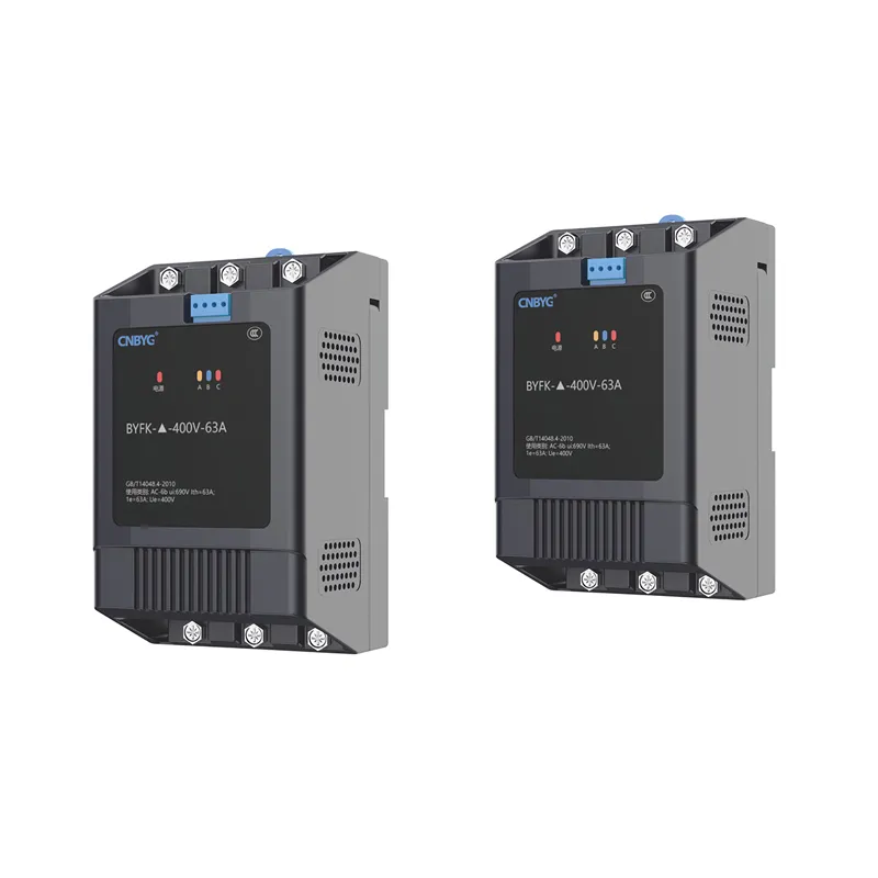
A composite switch and a contactor can both connect capacitor stages, but they control the transition differently. A capacitor-duty contactor is an electromechanical device commonly designed with a transient-limiting pre-insertion path. A low-voltage composite switch typically combines semiconductor-controlled transition with a mechanical holding path so closing and opening can occur near favorable waveform conditions while steady current avoids continuous semiconductor loss. Selection depends on step kvar, voltage, harmonic and reactor conditions, switching frequency, residual voltage, fault level, thermal environment, failure behavior, maintenance skills, control compatibility, and verified product ratings. Compare complete tested assemblies, not generic labels, before choosing a switching method.
- Separate the switching functions
- How a capacitor-duty contactor behaves
- How a composite switch behaves
- Compare response and switching frequency
- Harmonics, reactors, and waveform sensing
- Protection and failure behavior
- Maintenance and lifecycle comparison
- Selection and acceptance test
- Questions that reveal an incomplete comparison
- Use operating data to confirm the decision
- Tabla de decisiones
- Fuentes y lecturas adicionales
- Preguntas frecuentes
Separate the switching functions
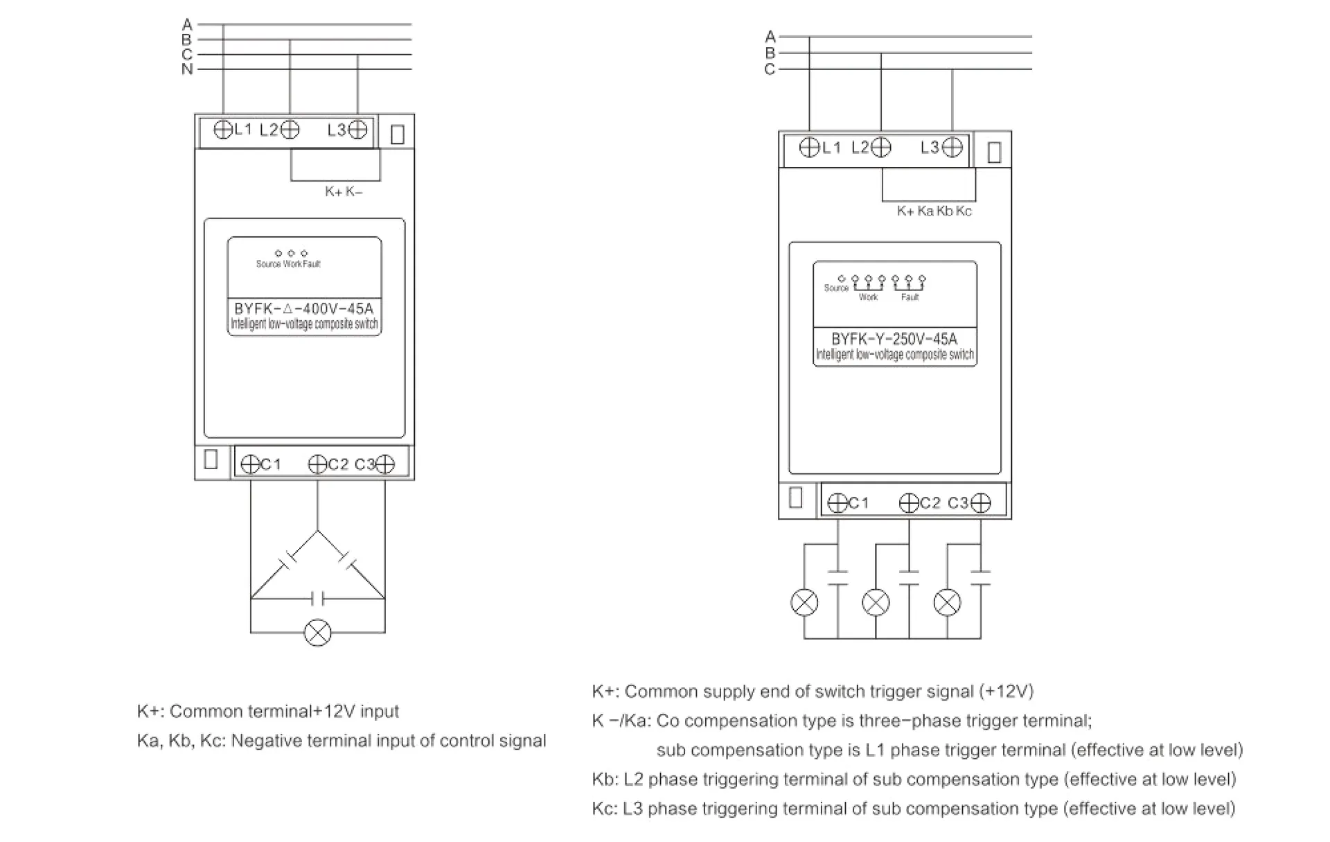
The switching device has at least three jobs: establish current without an unacceptable transient, carry continuous capacitor current, and interrupt at a controlled time without damage or unsafe residual conditions. A contactor performs these jobs mechanically, sometimes using early-make contacts and resistors to soften closing. A composite switch uses power electronics during the transition and a mechanical element for steady conduction in many designs. Exact topologies differ, so obtain the functional diagram and timing description for the specific device.
How a capacitor-duty contactor behaves

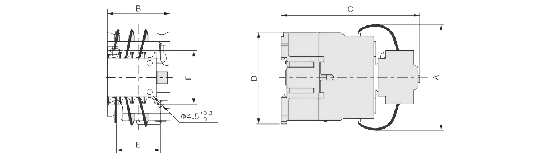
The contactor's strengths are familiar control practice, visible mechanical isolation state in some arrangements, established replacement procedures, and broad technician experience. Its contacts and damping components wear with operations and abnormal duty. Closing time is mechanical, and performance depends on coil voltage, mechanism condition, control timing, and the tested capacitor rating. It can be a strong choice for moderate switching frequency where the panel design respects discharge and inrush requirements.
How a composite switch behaves
A composite switch can use a thyristor or similar device to select a low-stress point for connecting or disconnecting, then transfer steady current to a low-loss mechanical path. This can reduce switching transients and mechanical contact wear when correctly coordinated. It also introduces electronic controls, voltage and phase sensing, semiconductor thermal limits, leakage or diagnostic considerations, and a particular failure mode that technicians must understand. The name composite switch does not prove zero transient or unlimited switching life; use declared test data and application limits.
Compare response and switching frequency
If load changes slowly, either method may follow demand with appropriately sized stages and controller delays. Frequent fluctuations make operation count and thermal duty more important. A composite design may support more frequent switching, but the capacitor still needs appropriate discharge and the stage should not chase every short event. A contactor can serve reliably when operations remain within its duty. For sub-cycle dynamic compensation, neither may satisfy the requirement; an SVG or another power-electronic compensator may be the relevant architecture.
Tabla de decisiones
| Punto de comparación | Capacitor-duty contactor | Composite switch | Decision evidence |
|---|---|---|---|
| Transition method | Mechanical closing, often with a defined pre-insertion path | Semiconductor-controlled transition plus mechanical steady path in many designs | Product functional diagram and test report |
| Steady conduction | Main mechanical contacts | Often mechanical bypass/holding path | Loss and temperature-rise data |
| Frequent operation | Limited by declared mechanical/electrical duty | May support higher frequency within electronic and thermal limits | Real load operation count and rated duty |
| Diagnostics | Coil, contacts, auxiliary feedback and visual inspection | Electronics, sensing, temperature, alarms and mechanical path | Maintenance procedure and spare strategy |
| Failure review | Contact welding, coil or resistor damage | Semiconductor, sensing, control or mechanical path failure | Declared safe state and protection coordination |
| Best fit | Stable to moderately varying stepped compensation | More frequently changing stepped compensation when validated | Complete system study, not device label |
Harmonics, reactors, and waveform sensing

Nonlinear loads can distort voltage and current, affecting both capacitor stress and a switch's detection of favorable switching instants. Detuned reactors change branch impedance and must be included in the approved assembly. Ask how the composite switch detects phase and residual voltage under distorted conditions, and how the contactor is rated with the reactor-capacitor branch. IEEE 519 addresses harmonic limits at the point of common coupling, but local switching-device stress requires equipment-level analysis.
Protection and failure behavior
Define what happens if a semiconductor fails short, a mechanical contact welds, control power disappears, phase sensing is lost, or an auxiliary contact disagrees with the command. Neither device substitutes for branch overcurrent protection and safe isolation. Coordinate fuses or breakers, fault withstand, upstream protection, discharge devices, and alarm feedback. Maintenance staff need an approved method to prove a stage is isolated and discharged. A no-click electronic transition must not be mistaken for a safe open circuit.
Maintenance and lifecycle comparison
Contactors invite inspection of contacts, coils, mechanisms, terminals, and damping components. Composite switches require checks of electronics, temperature, fans or heat sinks where present, sensing, firmware or parameter records if applicable, and mechanical bypass elements. Compare replacement time, spare availability, training, diagnostic tools, and whether one failed stage can be isolated without disabling the whole bank. Count expected operations from real load data rather than using an optimistic annual estimate.
Selection and acceptance test
Specify the capacitor and reactor assembly, bus conditions, fault level, operations, control signal, minimum off-time, ambient temperature, enclosure, communications, alarms, and required standards. Ask both suppliers to state continuous current, switching duty, transient limits, thermal derating, failure behavior, and test evidence on the same basis. During acceptance, verify correct stage command, balanced current, reactive-power change, temperature, alarms, discharge, and transient behavior using suitable instruments and an approved procedure. Keep the baseline for later maintenance.
Questions that reveal an incomplete comparison
Ask whether the quoted rating applies with the selected reactor, how residual capacitor voltage is detected, what happens when phase sensing is lost, whether the device provides a positive open-state indication, which upstream protective device was used in testing, and what replacement interval or operation counter is available. Ask for heat-loss data at enclosure conditions and the maximum permitted switching rate rather than a vague fast-switching claim. Finally, request the same stage-current, kvar-change, alarm, and failure-response acceptance test for both alternatives. If one supplier cannot state these boundaries, the devices are not yet being compared on equal terms.
Use operating data to confirm the decision
After commissioning, trend stage commands, feedback, bus power factor, reactive power, current, voltage, temperature, alarms, and switching count for representative production cycles. A composite switch should demonstrate the expected reduction in transition disturbance without exceeding thermal or frequency limits. A contactor should show stable coil operation, appropriate minimum off-time, and no rapid cycling or progressive heating. Compare the smallest step with actual kvar variation; poor step resolution can make either technology appear unstable. Review events after utility interruptions and control-power loss because residual voltage and restart sequencing can expose different behavior. The preferred device is the one that meets the stated acceptance criteria and remains understandable to maintenance staff, not the one with the fastest nominal response on a brochure. Preserve the trend interval, instrument source, units, and operating state so future comparisons use equivalent evidence.
How this topic connects to CNBYG equipment
This guide supports specification and commissioning discussions for the Composite switch product line. Product data must be checked against the actual system voltage, load profile, harmonic measurements, protection design, environmental conditions, and applicable project requirements. Share a single-line diagram and representative measurements before requesting a model recommendation.
Related CNBYG engineering guides
- review compound-switch records alongside an APF
- compare power and capacitor-duty contactors
- choose SVG or ASVG for dynamic sites
Fuentes y lecturas adicionales
El U.S. Department of Energy motor-driven systems guide explains where fixed and automatically switched power-factor correction can fit industrial load patterns. OSHA 1910.333 provides the U.S. baseline for de-energizing and electrical work practices. IEEE 519 is the standards-body reference for harmonic control at the point of common coupling. Apply the current editions and local requirements for the project.

Further learning: MIT OpenCourseWare Lecture 4: Power Factor. The MIT lecture explains power factor and distortion; it does not replace project-specific equipment instructions.
Preguntas frecuentes
Is a composite switch the same as a thyristor switch?
Not necessarily. Many composite devices use semiconductors for the transition and a mechanical path for steady current. Confirm the actual topology.
Does a composite switch eliminate capacitor inrush?
It can reduce switching transients when correctly applied, but performance depends on waveform sensing, residual voltage, network conditions and the tested design.
Which device is better for fast-changing loads?
A composite switch may tolerate more frequent stepped switching, but truly dynamic sub-cycle compensation can require an SVG rather than a capacitor stage.
Can either device be installed without branch protection?
No. Both require coordinated overcurrent protection, safe isolation, discharge provisions and fault-duty verification.
Final engineering note: Treat formulas and checklists as screening tools. Installation, protection, commissioning, and energized testing must be performed by qualified personnel using approved drawings, product manuals, studies, and site safety procedures.