


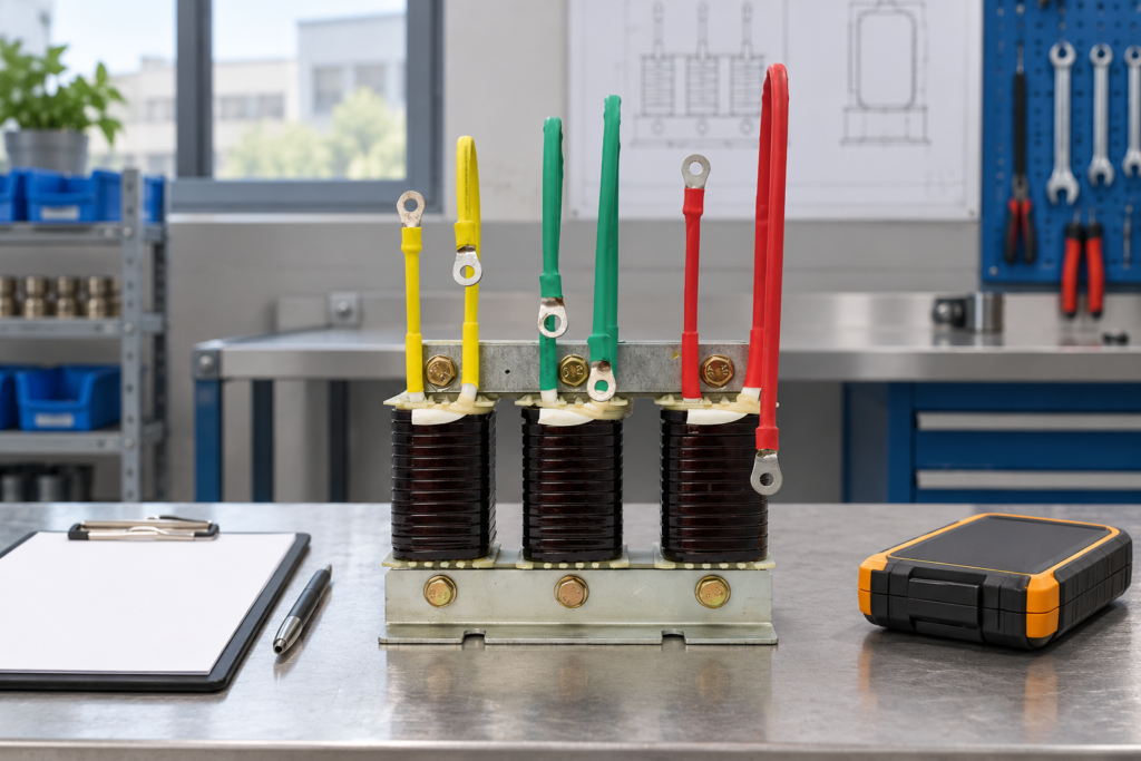
Detuned reactor temperature rise should be assessed against the supplied reactor’s measurement method, rated duty and installation conditions. A warm surface does not establish a winding temperature, and a thermal alarm does not identify its cause. Harmonic current, ventilation, ambient conditions, connection resistance, component mismatch and protection settings all need consideration. This guide explains how to build a repeatable investigation and verify the protective response of a low-voltage capacitor-bank reactor without inventing a universal safe temperature or bypassing an alarm.
Define which temperature is being reported
Distinguish winding temperature, accessible surface temperature, local air temperature and the cabinet’s remote sensor reading. These quantities can differ substantially and cannot be substituted without an agreed method. Record sensor location, instrument type, measurement time and operating state. A photograph with one temperature overlay is incomplete evidence if it omits the measurement settings and surrounding conditions.
Temperature rise is the difference between the specified component temperature and its reference ambient under the relevant method. A rise measured after a short light-load interval is not comparable with a rated steady-condition assessment. Ask the supplier for the definition, permitted duty and acceptance basis. The CNBYG CKSG series reactor family is a relevant enquiry starting point; the supplied model’s documents govern the actual installation and limits.
Treat the alarm as a protective event
Record the first event, operating mode, connected stages, currents, temperatures and controller response before resetting anything. Follow the installed equipment’s prescribed response. Do not disable, bridge or raise the protective setting to restore production without the responsible engineer’s approved assessment. An alarm can be correct even when the room feels cool, because its sensor may represent a different location or quantity.
Keep repeated resets visible in the event record. They can obscure the timing of a developing thermal problem. If a shutdown is required, use the site’s qualified procedure and consider the capacitor bank’s stored energy. prácticas de trabajo eléctrico de OSHA describe hazardous stored-energy control and verification in their jurisdiction. This article does not authorize access to energized windings or provide an improvised cooling repair.
Establish a comparable baseline
Collect the original reactor and capacitor identities, percentage definition, voltage, frequency, current duty, protection arrangement and installation drawing. Record cabinet inlet conditions, ventilation path and neighbouring heat sources. Compare the observed installation with the approved design. A changed fan, filter, partition or adjacent device can alter cooling without changing the electrical nameplate.
If the commissioning record exists, reproduce its operating boundary as far as practical under the approved procedure. Note any unavoidable differences. If there is no baseline, ask the manufacturer for the expected measurement conditions rather than declaring the present reading normal. A documented starting point allows later maintenance to distinguish a real change from a different measurement location or production load.

Separate electrical duty from cooling duty
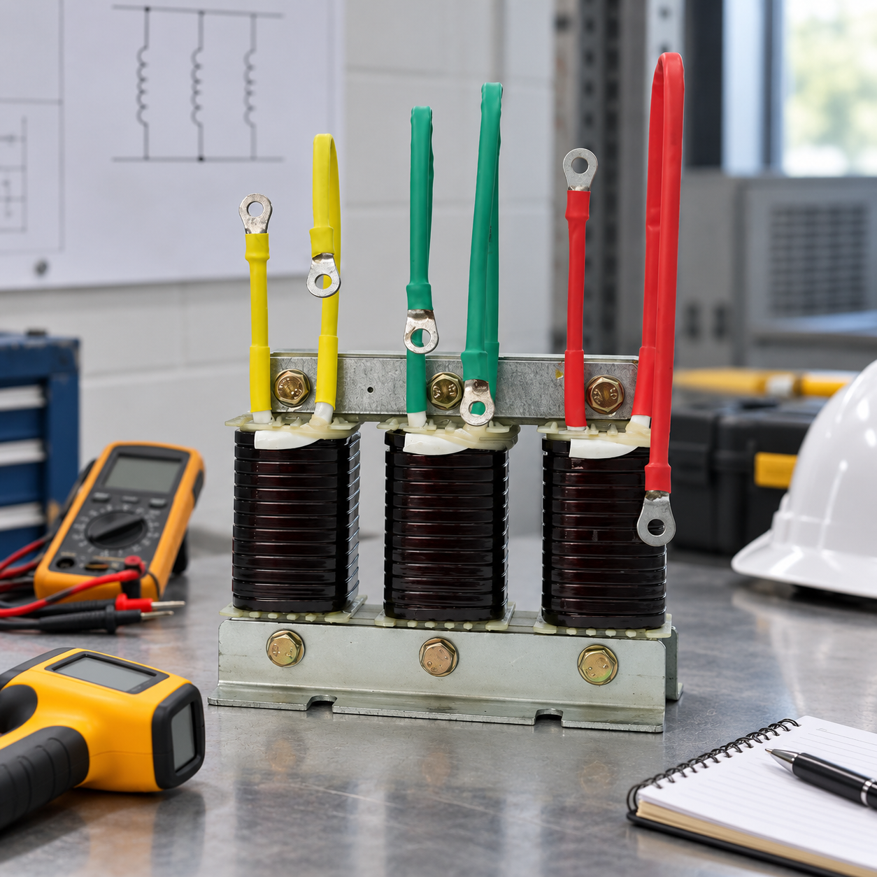
Record total RMS branch current, relevant harmonic components and stage state together. Fundamental current alone can miss additional harmonic duty. The relationship between voltage, current and reactance is introduced in OpenStax’s AC circuit lesson. Actual reactor losses depend on construction and frequency-dependent behaviour, so do not convert a single current increase into a universal temperature prediction.
Compare demanding production periods and supply configurations. Drives, transformer changes, generator operation and other capacitor stages can change the spectrum and network response. If the event appears only with one configuration, retain that configuration as an explicit investigation input. The reactor-in-capacitor-bank guide explains why the reactor belongs to a coordinated branch rather than an independent accessory.
An investigation table with useful comparisons
The table directs evidence collection without supplying arbitrary temperature thresholds. The public scope of IEC 60076-6 includes several reactor categories, including filter reactors. Agree the applicable requirements and actual thermal limits for the supplied equipment with its manufacturer and responsible engineer.
| Observed pattern | Possible explanation | Comparison that helps distinguish it |
|---|---|---|
| All stages hotter during production | Higher duty or poorer cabinet cooling | Current spectrum, inlet temperature and airflow at the same operating state |
| One connection markedly hotter | Local connection resistance | Termination condition and comparable joints under an approved method |
| Alarm follows a fan or filter change | Changed cooling path | Before-and-after installation and ventilation evidence |
| Alarm follows capacitor replacement | Changed branch match or current | Old/new capacitance, reactor identity and coordinated branch calculation |
| Sensor changes without electrical change | Measurement or control-path problem | Independent suitable measurement and sensor/control verification |
| Event only in generator mode | Different supply and spectrum | Configuration-specific duty and network assessment |
Inspect the complete ventilation path
Trace air from inlet to outlet and identify restrictions, recirculation and obstructions. A running fan does not prove that useful air reaches the reactor. Check filters, blocked grilles, cabinet partitions and equipment spacing through the approved safe-access procedure. Confirm the fan arrangement and direction against the design instead of changing it by trial and error.
Review the total cabinet heat load. Several components can share the cooling system, and a newly installed device can affect a previously acceptable reactor position. Record local air conditions near the component rather than relying only on a remote room sensor. After a cooling repair, verify performance during representative sustained duty; a brief open-door observation does not establish normal closed-cabinet operation.
Distinguish winding heating from a bad connection
Local terminal heating can reflect an installation or connection fault rather than excessive losses throughout the reactor. Photograph the pattern and compare corresponding points using an appropriate method. Reflective surfaces, viewing angle and instrument settings can affect thermal imaging interpretation. A hotspot is a reason for a qualified investigation, not proof of a particular loose joint.
Any termination work must follow the supplied instructions, including conductor arrangement and specified fastening requirements. This guide supplies no universal torque value. Preserve what was found before repair and record what was changed. A later comparable operational check should show whether the local problem was resolved without hiding a separate winding or ventilation issue.
Check component matching after maintenance
Review all capacitor and reactor replacements since the accepted baseline. The detuning relationship depends on both inductance and capacitance. Fitting a physically similar capacitor can alter branch current, frequency response and voltage conditions. Confirm the actual ratings and connection rather than relying on the work order’s description of a like-for-like replacement.
The low-voltage self-healing capacitor standards family is described by IEC 60831-1. Product-specific limits and the coordinated design remain necessary. When a mismatch is suspected, ask the engineer to assess the full branch and protective devices before reconnecting it. Keep the accepted component pairing in the capacitor-bank maintenance records so the same mistake does not recur at the next replacement.

Verify the sensor and protective response separately
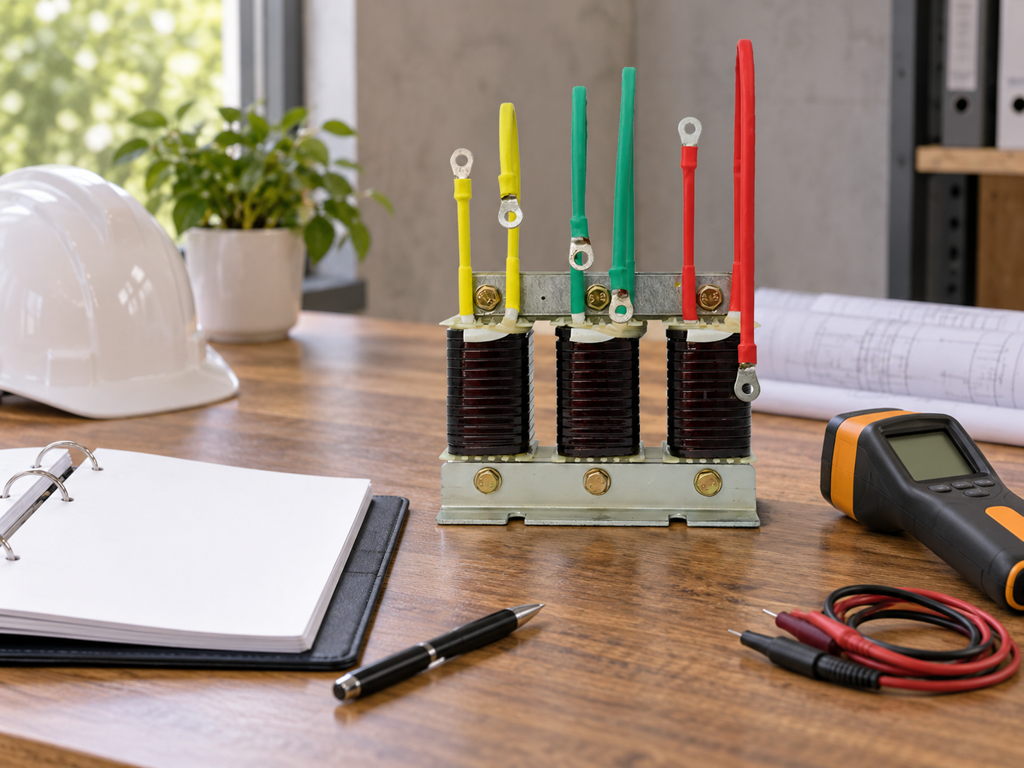
Identify whether protection uses a thermostat, thermistor, embedded sensor or another arrangement, and obtain its specified behaviour. The wiring and controller logic should match the supplied design. A displayed temperature and a functioning protective trip are different checks. Confirm how the signal is interpreted, what action it commands and what response is expected if the sensing circuit has a fault.
Have qualified personnel verify the protective path using the approved test method. Record stimulus, indication, command, actual stage response, alarm retention and reset requirements. Do not heat equipment beyond its permitted conditions merely to see whether it trips. Never replace an approved protective test with an assumption that a visible alarm icon proves the branch disconnected correctly.
Close the cause review with a focused acceptance test
Write a cause statement that distinguishes confirmed observations from unresolved alternatives. For example, a documented blocked filter is a confirmed finding, while its contribution to the alarm may still need operating verification. A replacement reactor with a different temperature reading does not automatically prove the original one was defective; installation and load differences may explain the change.
Define the post-repair operating boundary before testing. Record stage state, spectrum, inlet conditions, measurement method, sustained duty and protective function. The capacitor-bank safety guide remains relevant to access and stored-energy control. Keep any untested supply or production mode as an open follow-up rather than claiming unrestricted acceptance from a limited test.
Build the next review around the mechanism
For a cooling issue, inspect the actual airflow path and repeat the thermal comparison during demanding operation. For changed harmonic duty, review the relevant spectra and configurations. For a local connection fault, retain comparative connection evidence. For a sensor-path fault, preserve the protective test and control response. These targeted checks are more useful than a calendar reminder that merely says to inspect temperature.
Maintain the original event timeline and record each repair separately. Include who approved the operating decision and which evidence justified it. This makes later alarms easier to assess and prevents a sequence of resets, component swaps and setting changes from erasing the initial cause. A good investigation finishes with traceable operating evidence and a clear trigger for the next action.
Educational video: inductor fundamentals
The Engineering Mindset explains inductors and their basic electrical behaviour. It provides background for reactor duty, not an industrial thermal-test method or permission to change protection settings. Follow the supplied component documentation and qualified project procedure.

Preguntas frecuentes
Is one surface temperature enough to judge a reactor?
No. Identify the quantity, location, operating state and acceptance method. A surface measurement is not automatically a winding temperature.
Can the alarm setting be raised to stop trips?
Do not alter or bypass protection without an approved engineering assessment. Investigate duty, cooling, component matching and the sensing path first.
Can capacitor replacement cause reactor heating to change?
Yes, if the coordinated branch or operating duty changes. Verify the actual capacitor/reactor match and compare current and spectrum with the accepted baseline.
What proves a thermal repair worked?
Comparable measurements under representative operation, verification of the protective response and a documented cause review. Record untested modes as open follow-ups.