Cómo seleccionar un condensador de potencia de baja tensión
Seleccione un condensador de potencia de baja tensión en función del voltaje del sistema medido, kvar requeridos, conexión, armónicos, carga de conmutación, temperatura, protección y requisitos del producto aplicables. No elija solo por la etiqueta nominal del bus o un factor de potencia deseado. Un condensador adecuado debe proporcionar el soporte reactivo previsto sin estrés excesivo en el voltaje, resonancia, corriente de arranque, calor o operación en modo de liderazgo en cargas ligeras.
El familia de condensadores de potencia cilíndricos CNBYG BSMJ proporciona contexto para la compensación dinámica cuando un condensador fijo no es suficiente. La selección final del condensador corresponde al diseño eléctrico, datos del fabricante y estudio del sitio.
Defina primero la aplicación
Marque la conexión del condensador en el diagrama unifilar y indique si el banco está en un alimentador de motor, MCC, secundario del transformador o PCC. Registre el voltaje nominal de línea a línea, frecuencia, disposición de fases, tomas del transformador, tolerancia de voltaje, nivel de cortocircuito y corriente de falla disponible. Liste motores, VFDs, rectificadores, soldadores, sistemas UPS, inversores solares, cargadores de vehículos eléctricos y otras fuentes armónicas.
Mida kW, kvar firmado, voltaje, corriente, factor de potencia real, factor de desplazamiento, THD, órdenes armónicas, temperatura y estado de carga. Incluya condiciones mínimas, normales, pico, de arranque, de parada y de transición.
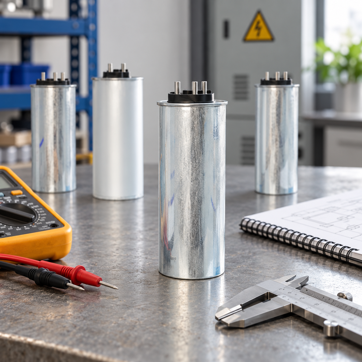
tabla de selección
| Factor de selección | Pregunta | Evidencia |
|---|---|---|
| Voltaje | ¿Qué voltaje máximo continuo y transitorio puede ocurrir? | Estudio de voltaje, rango de tomas y medición. |
| kvar | ¿Qué soporte reactivo neto se requiere en el límite? | kW medidos, kvar, FP y banda objetivo. |
| Conexión | ¿Cada condensador ve el voltaje de fase previsto? | Dibujo unifilar y de conexión aprobado. |
| Armónicos | ¿El banco puede resonar o sobrecalentarse? | Espectro armónico y estudio del reactor. |
| Conmutación | ¿Con qué frecuencia conmutan las etapas y qué corriente de arranque ocurre? | Configuraciones del controlador, contactor o tiristor. |
| Entorno | ¿Qué ambiente, recubrimiento y enfriamiento se aplican? | Distribución, ventilación y límites del fabricante. |
| Protección | ¿Están coordinados fusibles, disyuntores, descarga y alarmas? | Estudio de protección y pruebas de puesta en marcha. |
Calcule los kvar requeridos
Estime la corrección neta a partir de la potencia activa medida y el factor de potencia inicial y objetivo:
Q_c = P × [tan(arccos(PF₁)) − tan(arccos(PF₂))]. Q_c es la compensación requerida en kvar, P es la potencia activa en kW, y PF₁/PF₂ son los factores de potencia de desplazamiento inicial y objetivo. Aplique la fórmula solo al límite definido y en la condición de operación apropiada.
Use unidades consistentes y el mismo límite. Reste los kvar del condensador firmado existente e incluya la demanda de magnetización del transformador. Calcule estados separados para carga mínima, normal y pico. Un banco dimensionado para producción máxima puede ser excesivo cuando el proceso se detiene.
El Requisitos de seguridad para bancos de condensadores Explica por qué el voltaje afecta la corriente para un kvar dado. Si la carga cambia rápidamente, utilice pasos o soporte dinámico en lugar de una etapa fija grande.
Verifique armónicos, reactores y conmutación
Los condensadores pueden interactuar con la inductancia del transformador y del sistema. Revise armónicos de voltaje, corriente y resonancia antes de conectar el banco. Si se usa un reactor desacoplado, confirme la afinación, corriente continua, temperatura y el voltaje del condensador resultante. No copie un porcentaje de reactor de otra planta.
Verifique la conmutación del contactor o tiristor, corriente de entrada, tiempo mínimo de encendido/apagado, descarga, fusibles y coordinación del disyuntor. El propósito de los reactores en bancos de condensadores proporciona verificaciones relacionadas con los límites de medición. El Guía de requisitos de instalación de SVG cubre enfriamiento y acceso.

Seleccione pasos y comportamiento de control
Elija tamaños de pasos que coincidan con la variación de carga. Defina un margen muerto, retardo, carga mínima, límite de avance y respaldo. Si un SVG, relé APFC y inversor comparten un límite, asigne un controlador primario en cada modo. Para exportación de generador o solar, revise el objetivo por separado.
El Lista de verificación para la puesta en marcha de SVG puede estructurar pruebas de fase, CT, protección y alarma. El lista de verificación de mantenimiento de bancos de condensadores ayuda a preservar configuraciones y registros de temperatura.
Secuencia práctica de selección
- Marque el límite del condensador y la conexión.
- Confirme el voltaje, frecuencia, fase y rango de derivación.
- Mida kW, kvar, PF, voltaje, corriente y armónicos.
- Calcule el kvar neto para estados mínimo, normal y pico.
- Enumere los condensadores, reactores y compensadores existentes.
- Verifique resonancia, corriente de inrush, conmutación, temperatura y protección.
- Seleccione voltaje, kvar, tamaño de paso y jerarquía de control.
- Pruebas de inicio, parada, carga mínima y carga máxima.
- Registre voltaje, corriente, THD, alarmas y temperatura.
- Guarde las configuraciones restantes y revise los disparadores.
Errores comunes
Do not select from nominal voltage alone. Do not ignore connection or harmonics. Do not use nameplate kW instead of measured load. Do not leave a fixed stage connected at light load without checking leading kvar. Do not assume a detuned reactor removes every resonance risk. Do not omit discharge, protection or cooling.
Record the selection assumptions
Keep the selected voltage, frequency, connection, kvar, step size, reactor arrangement, temperature class, protection and discharge data in one record. Add the measured voltage range, harmonic spectrum, transformer tap and minimum-load state. If a value is estimated, mark the estimate and schedule the measurement before final energization. This prevents a replacement capacitor from being ordered from an old nominal label after the system has changed.
Compare the selected kvar with the measured signed kvar at minimum, normal and peak load. Confirm that the bank does not create leading PF when the process stops and that the controller can block a stage. If the plant operates on a generator, solar inverter or battery, repeat the check for each source mode. The same fixed stage can be acceptable on utility power and inappropriate on a lightly loaded generator.
For procurement, request the complete data sheet, drawings, declarations, temperature and harmonic limits, reactor details, discharge method, protection recommendations, switching duty and maintenance instructions. Keep the approved alternative and the reason for rejection of other ratings. During commissioning, test each stage, record voltage and current, verify protection and save the as-left controller settings.
Review the selection after a new VFD, rectifier, UPS, transformer, solar inverter or EV charger is added. A new harmonic source can change current, resonance and temperature without changing the nominal bus voltage. The maintenance record should identify the next review trigger and the responsible person.
Verify the as-built connection
Before energization, compare the installed connection with the approved drawing. Confirm phase labels, neutral treatment, reactor location, discharge circuit, CT direction, fuse or breaker settings and the stage order. A correct component on the wrong side of a CT can make the controller increase rather than remove reactive current. A correct bank with a different transformer tap can also deliver a different kvar than the design estimate.
Use an independent analyzer for the first stage test. Record the voltage, current, signed kvar, PF, THD, temperature and alarm state before and after switching. Wait for the stage to settle before comparing. Repeat after the load changes and at the minimum normal load. If a stage is blocked, record the reason instead of treating the missing kvar as a failed capacitor.
The selection should also state what happens when the target cannot be reached. The controller may relax the PF band, preserve harmonic priority, block a stage or alarm at a current limit. Operators need that behavior before a production change occurs. Keep the previous setting and rollback value, and define the person who can approve a new stage size. This is particularly important when the plant switches between utility, generator, solar export and battery modes.
At handover, give maintenance the approved drawing, calculation inputs, capacitor and reactor data, protection settings, discharge procedure, stage sequence, temperature limits and review triggers. The next reviewer should be able to determine whether a new VFD, transformer tap or load schedule invalidates the selection without rebuilding the entire study.
Keep a clear distinction between the calculated net kvar and the bank’s nameplate kvar. Existing capacitors, transformer magnetizing current and other compensators can change the net result. If the plant has rapid load changes, show which portion is handled by fixed steps and which portion is handled dynamically. This makes future troubleshooting faster and reduces the risk of adding a second controller with a conflicting boundary.
The selection record should also show the maximum current and voltage used for the check, not only the nominal values. Keep the approved step sequence, leading block, alarm behavior and rollback beside the data sheet so the bank can be serviced without guessing.
If the bank cannot meet the requested target at the lowest voltage, record the limitation and choose whether to relax the band, reserve current for harmonics, add capacity or change the boundary. Do not conceal an unavailable target by changing the meter definition.
Keep the decision with the as-left record.
Include the reviewer and test date.
Keep the raw analyzer file.
Record the final alarm state.
Keep the test conditions.
Keep the approved drawing.
Attach the calculation file.
Keep the source measurements.
Keep the as-left settings.
Keep the signed acceptance sheet.
Source boundaries for capacitor selection
IEC 60831-1 identifies the standards family for self-healing low-voltage shunt capacitor units and banks. Use the applicable requirements and the installed product documentation; a standards catalogue summary is not an acceptance procedure. OpenStax explains capacitor reactance and AC behaviour, which underpin the voltage, frequency and capacitance relationships. For reactor-equipped banks, assess the matched branch and harmonic duty rather than treating the capacitor as a bare element.
prácticas de trabajo eléctrico de OSHA address hazardous stored energy and verification in their jurisdiction. Qualified personnel must follow the approved local isolation and discharge procedure; capacitor selection does not establish that an existing bank is safe to access.
For spares awaiting installation, use the power-capacitor storage and incoming-inspection guide.
Preguntas frecuentes
What is the first capacitor-selection input?
Antes de elegir la potencia nominal del producto, defina los límites de conexión, la tensión, la frecuencia, el perfil de carga y los kvar netos medidos.
¿Son siempre mejores pasos de kvar más grandes?
No. Large steps can cause overcorrection and switching transients. Match steps to load variation and use a stable deadband.
¿Cuándo es preferible un SVG dinámico?
When reactive demand changes quickly, harmonics share current, or fixed stages would become leading at light load.
¿Qué demuestra que la selección es segura?
Measured voltage, current, harmonics, temperature, protection, switching and PF results across minimum, normal and peak states.
Conclusión
Low-voltage power-capacitor selection is a system study, not a nominal-voltage lookup. Match voltage, kvar, connection, harmonics, reactors, switching, environment and protection to measured operating states, then test the bank across the full load range.
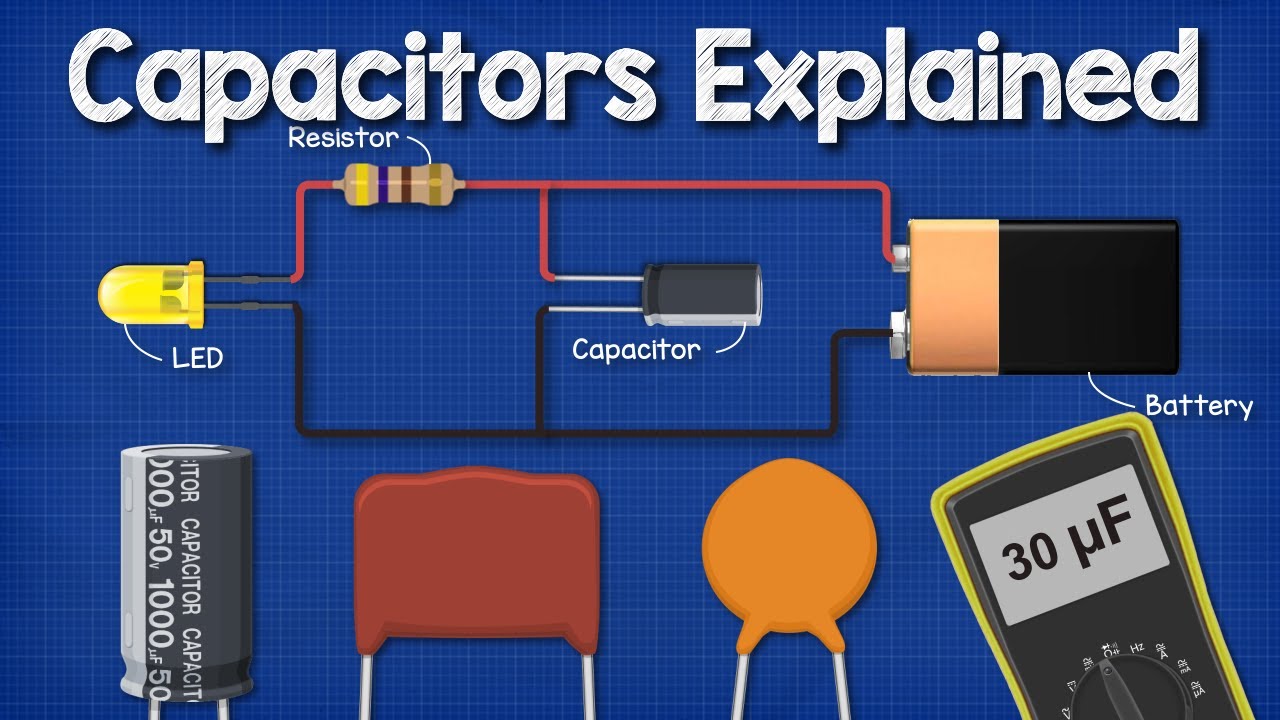
Educational video: capacitor fundamentals
The Engineering Mindset explains capacitor charge storage and basic behaviour. Small-component demonstrations are conceptual background, not an industrial testing or discharge procedure.