What Type of Contactor Is Used with a Capacitor Bank?
For a capacitor bank, the power contactor vs capacitor duty contactor choice should follow the switching duty: use a manufacturer-rated capacitor-switching or AC-6b contactor for the capacitor stage, and select an ordinary power contactor only for the resistive or motor duty stated for that device. Similar steady-current ratings do not make the two categories interchangeable. Load duty and the energization event establish the correct category; stage and control data then narrow the final model.
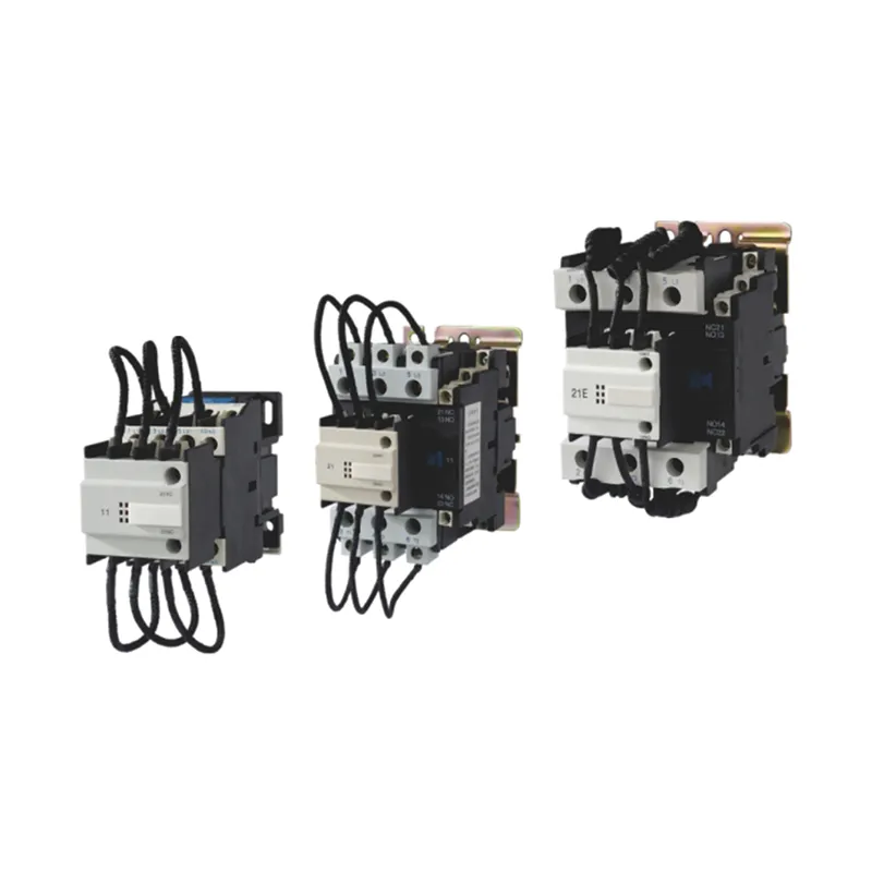
Power Contactor vs Capacitor Duty Contactor: The Decision at a Glance
Choose by load duty: a general power contactor serves the ordinary-load category printed in its documentation, while a capacitor-duty contactor is intended and rated for capacitor-bank switching.
A power contactor’s suitability is tied to a utilization category, which describes the kind of load and switching event it is expected to handle. A capacitor-duty contactor is the specialized branch of that device family used for a PFC capacitor stage, where the closing event is more demanding than the later steady current suggests.
| Decision point | Ordinary power contactor | Capacitor-duty contactor |
|---|---|---|
| Typical load decision | Resistive, slightly inductive, or motor load according to the stated category | Capacitor bank or PFC capacitor stage |
| Category to examine | Often AC-1 or AC-3, depending on the load | AC-6b or explicit capacitor-switching duty |
| Making-duty concern | Must match the documented behavior of the ordinary load | Must address the energization peak of the capacitor stage |
| Contact arrangement | Standard main-contact arrangement for the stated duty | Some families add early-make contacts and current-limiting resistors |
| Selection evidence | Load type, operating current, voltage, coil data, and category | Stage data, voltage, switching arrangement, coil data, making capability, and exact product table |
Consider a purchase list containing two devices with similar ampere figures. If one is cataloged for squirrel-cage motor duty and the other for capacitor-bank switching, the labels describe different jobs. The ampere figure remains important, but it belongs inside the duty-category decision rather than replacing it.
Why Capacitor-Bank Energization Changes the Contactor Duty
The first instant of capacitor energization creates a making-current stress that a steady-current label does not describe.
Capacitor energization creates a short-duration high-current making event. This inrush current reaches the contacts during making, so a selection based only on the current after the transient misses the event that separates capacitor duty from ordinary load duty.
In an automatic power-factor-correction panel, an APFC controller determines when a capacitor stage is commanded. The contactor still has to perform the capacitor-switching duty on every closure.
That distinction matters during replacement. A panel builder may have a familiar motor contactor with a matching steady-current label on the shelf, but its motor-duty documentation does not establish capacitor-bank making capability. The replacement decision has to return to the load category and the manufacturer’s capacitor-switching data.
Read AC-1, AC-3, and AC-6b Before Comparing Current Ratings
AC-1, AC-3, and AC-6b identify different load behaviors; AC-6b is the utilization category for capacitor-bank switching.
A utilization category links contactor making and breaking performance to a defined application. In plain language, the AC code tells procurement what kind of load the device is built to switch, not merely how many amperes appear beside the model name.
| Utilization category | Application meaning | Decision error it prevents |
|---|---|---|
| AC-1 | Non-inductive or slightly inductive AC loads | Treating a resistive-load rating as a motor or capacitor-bank rating |
| AC-3 | Squirrel-cage motor starting and interruption during normal running | Treating a motor-duty contactor as a capacitor bank contactor |
| AC-6b | Switching capacitor banks | Selecting from steady current without confirming capacitor-switching duty |
AC-6b identifies switching of capacitor banks in the utilization-categories overview. It gives the buyer the correct category starting point, while the final model still has to match the stage and control data.
If the unanswered question is how a coil, armature, and main contacts produce the switching action, see how the CJ19 contactor works. That operating-principle question is separate from deciding which utilization category belongs on a capacitor stage.
How Early-Make Contacts and Damping Resistors Protect the Main Switching Path
In documented capacitor-contactor families, an early path and resistor can limit the initial peak before the main contacts close.
An early-make contact closes before the main power contacts. When that path contains damping or current-limiting resistance, the stage first connects through the resistor; the main contacts then close and carry the normal current. In product families built this way, the pre-closing path limits current before the main path closes.
Looped leads and upper assemblies can make a capacitor switching contactor look different from an ordinary contactor. Their electrical role comes from the documented contact sequence rather than appearance alone.
The arrangement is product-family specific. A Schneider TeSys family uses early-make poles with damping resistors, while CNBYG documents a pre-closing current-limiting circuit for its GJ19/CJ19 family. Other capacitor-contactors may use a different documented arrangement, so construction should be read from the product data rather than inferred from the category name alone.
Select a Capacitor Contactor from Duty, Stage, Voltage, and Control Data
Start with capacitor-duty or AC-6b documentation, then match the stage voltage, kVAR or current, switching arrangement, coil supply, mounting, and the model-specific making data.
The duty category answers “which kind of contactor?” The project inputs answer “which model?” A buyer who has only a capacitor-stage kVAR value is missing the voltage and control information needed to connect those two decisions.
| Input to collect | Why it changes the choice | Where to compare it |
|---|---|---|
| System voltage and frequency | Establishes whether the product family and rating table apply | Product electrical data |
| Capacitor-stage kVAR or operating current | Identifies the stage duty at the stated voltage | Model table for that voltage |
| Stage arrangement and switching sequence | Describes what the contactor connects and how the bank is stepped | Panel design and capacitor-switching documentation |
| Utilization category | Confirms that the stated rating belongs to capacitor-bank duty | Category or application-rating line |
| Published making or inrush capability | Addresses the closing event that steady current omits | Manufacturer’s exact family data |
| Coil voltage and frequency | Matches the controller or control-power supply | Coil and ordering table |
| Mounting and terminal arrangement | Confirms mechanical and wiring compatibility | Dimension and installation document |
| Exact model revision | Keeps all ratings tied to the item being ordered | Current datasheet and product table |
The connection schematic below is a document-reading aid for CJ19-63/21 and CJ19-95/21 arrangements. It is not a substitute for the project’s wiring drawing or the electrical data for the selected model.
One universal multiplier cannot replace these inputs. Published making capabilities and capacitor ratings stay with the named product family and stated conditions. Compare the actual stage record with the applicable model table rather than transferring one family’s value to another.
Calculating the compensation value still leaves a practical specification gap. In this capacitor-bank practitioner discussion, the question moves to staging, sequence, and control inputs—the same information needed beside the electrical rating.
Avoid Ampere-Only, kVAR-Only, and Photo-Only Selection
A current number, a kVAR label, or a product photograph cannot by itself establish category and model compatibility.
Ampere-only selection overlooks utilization category and making duty. kVAR-only selection overlooks the voltage at which the stage rating applies, along with coil supply and switching arrangement. Both shortcuts can produce a model that appears plausible in a spreadsheet but belongs to a different electrical job.
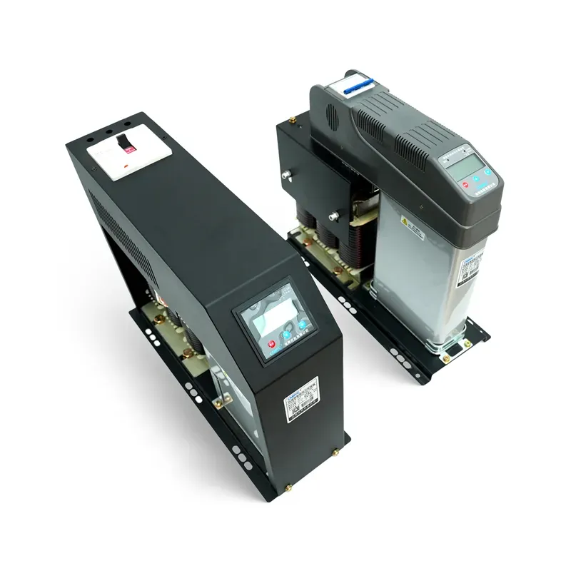
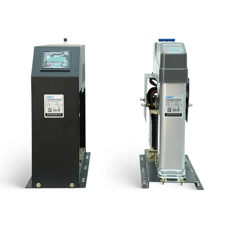
Appearance answers a narrower question. A photograph cannot identify the utilization category, confirm capacitor-switching capability, or supply the electrical data needed for model selection. Read the nameplate and category first, then compare the stage and control data with the product information for that model.
Important : A calculated kVAR or current value is not a complete capacitor-contactor specification. Carry the stage arrangement and control sequence into the decision. Match voltage and model-specific data to the product table, and confirm the utilization category separately.
Another common shortcut is transferring one product family’s inrush claim to a different model. A published peak capability is useful only with the family, category, voltage, and test conditions to which it belongs. For procurement, this means comparing like-for-like rows rather than turning the largest number in a search result into a universal rule.
Where the CNBYG GJ19 Fits—and When to Escalate the Duty Review
GJ19 is the relevant CNBYG capacitor-switching family to review; move to a harmonic-network duty assessment when reactors, harmonics, switching records, or topology determine the question.
La GJ19 Series switching capacitor contactor is presented for switching low-voltage parallel capacitors. Its product information describes an upper current-limiting contact and resistor circuit that connects before the working contacts, and it supplies model and coil-ordering data for the next selection step.

Review that family when the load is a capacitor stage and the project inputs can be compared with its product table. Do not select it merely because its current resembles an ordinary power contactor, and do not treat it as the answer to a motor-load or general resistive-load requirement. The broader compensateur de puissance réactive page places the contactor beside the other components used in compensation systems.
The decision becomes a system-duty question when a detuned bank, reactors, harmonic-producing loads, controller sequence, or measured switching records shape the stress. When harmonic conditions or reactor topology determine contactor stress, continue with the capacitor switching contactor duty review for harmonic networks before fixing the contactor model.
FAQ
Why use a capacitor-duty contactor?
Use it because capacitor-bank energization creates a distinct making-current peak. A capacitor-duty contactor is rated for that switching job, and some documented families add a pre-closing resistor path to limit the initial peak.
What is a capacitor-duty contactor?
It is a contactor intended for switching capacitor banks or PFC stages. Its application category, making capability, and product construction are documented for capacitor duty rather than inferred from an ordinary-load ampere rating.
Can a normal power contactor switch a capacitor bank?
Only when the exact manufacturer documentation approves that device for the capacitor-switching duty and the stage conditions. A motor-duty or resistive-load rating with a similar current value is not enough to establish that fit.
What does AC-6b mean on a contactor?
AC-6b is the utilization category for switching capacitor banks. It separates capacitor-bank duty from AC-1 resistive or slightly inductive duty and AC-3 motor duty.
Is AC-3 the same as capacitor duty?
No. AC-3 applies to squirrel-cage motor duty, while AC-6b applies to capacitor-bank switching. The two codes describe different load behavior and should not be substituted on current rating alone.
Does a contactor supply reactive power to the capacitor?
No. The contactor connects or disconnects the capacitor stage from the power circuit. The energized capacitor supplies reactive power; the contactor performs the switching action.
How should I choose the contactor size for a capacitor bank?
Confirm capacitor-duty or AC-6b suitability, then match system voltage, stage kVAR or current, switching arrangement, making capability, coil supply, mounting, and the exact manufacturer’s model table. Avoid a cross-manufacturer sizing multiplier.
Are early-make contacts and resistors used in every capacitor contactor?
Not necessarily. They are documented in specific capacitor-contactor families, including the GJ19/CJ19 arrangement discussed here. Read the construction and sequence for the exact family being considered.
When does a comparison become a harmonic-network duty review?
Escalate when harmonics, reactors, detuning, switching records, or bank topology influence the contactor stress. Those conditions require a system-level duty assessment rather than a category comparison alone.
Références
Practical FAQ
What type of contactor is used with a capacitor bank?
Use a capacitor-duty contactor rated for the bank kvar, system voltage, inrush duty, switching frequency, ambient conditions, and protection scheme.
Can an ordinary motor contactor switch capacitor steps?
Do not assume so from continuous amperes. Capacitor energization has high inrush and requires a published capacitor-duty rating.
Why do capacitor contactors use early-make contacts?
They insert an impedance briefly to limit inrush before the main contacts carry steady capacitor current.
What does AC-6b mean?
AC-6b is the utilization category associated with switching capacitor banks under the applicable low-voltage contactor standard.
When should thyristor switching be considered?
Consider it for fast-changing loads or high switching frequency after checking losses, cooling, harmonics, and protection.