SVG vs SVC for Industrial Reactive Power Compensation
SVG vs SVC for Industrial Reactive Power Compensation
An SVG vs SVC comparison must begin with voltage level, connection point and system purpose. In low-voltage industrial distribution, “SVG” commonly describes a modular converter-based static var generator installed near plant loads. An SVC is a shunt-connected compensation system built from thyristor-controlled or switched reactors and capacitors, often used at medium or high voltage. Both regulate reactive power, but their architecture, footprint, filtering, response, losses, studies and maintenance scope differ. Do not select from the acronym alone; define the network problem and compare engineered systems at the same bus.
Clarify the terminology before comparing bids
SVG is often used commercially for a converter-based device in the STATCOM family. Naming varies by supplier and market. The proposal should identify the converter topology, rated voltage, current or kvar capability, connection arrangement, and supported functions. Do not infer an IEEE equipment class from the product name alone.
An SVC normally combines controlled or switched reactive branches, such as thyristor-controlled reactors and thyristor-switched capacitors, with filters and protection. Its station can include substantial primary equipment and civil works. An industrial buyer comparing a cabinet SVG with a utility SVC is not comparing equivalent packages; the project scale and connection voltage may be entirely different.
La Page produit CNBYG SVG represents the low-voltage modular product context for this article. Exact ratings and functions must be confirmed from the selected model’s current documentation.
Functional comparison
| Question | Modular converter-based SVG | Thyristor-based SVC | Project evidence |
|---|---|---|---|
| Typical project context | Local or distributed compensation near low-voltage industrial loads | Bus-level compensation engineered as a larger station or system | Voltage level, short-circuit study and one-line diagram |
| Reactive output | Controlled converter current within thermal and current limits | Controlled combination of reactor and capacitor branches | Required inductive/capacitive range over bus voltage |
| Footprint | Wall or rack modules plus cabinet, CTs and protection | Branches, filters, switchgear, cooling and civil area | Layout, clearances, access and environmental constraints |
| Harmonic design | Converter spectrum and network compatibility require review | Thyristor operation and passive branches make filters a system-design item | Impedance scan, background distortion and applicable limits |
| Expansion | May use parallel modules when the design supports coordinated sharing | Expansion changes branch and station studies | Growth cases, redundancy philosophy and available space |
| Maintenance | Module electronics, fans, filters, controls and connection checks | Valves, reactors, capacitors, filters, cooling and station apparatus | Skills, spares, outages and service organization |
The table is directional, not a substitute for supplier curves or a system study. A large converter-based STATCOM and a small industrial SVG can share a principle but have very different engineering scope.
Voltage and system strength shape performance
Specify the required reactive range across the actual bus-voltage envelope. A converter-based device is current-limited; its available kvar changes with operating voltage and thermal condition. An SVC’s passive branch output has a stronger voltage relationship, while its controlled reactor changes net output. The correct comparison uses the supplier’s performance envelope, not one nameplate point.
System strength also matters. Obtain short-circuit level and impedance information at the proposed connection point. Weak systems, background harmonics and nearby compensation can affect controls and resonance. A qualified power-system study should assess the operating cases, contingencies and coordination with protection.
IEEE 1031 is a guide for functional specification of transmission static var compensators. It helps frame SVC requirements, but it does not turn a low-voltage cabinet SVG into a transmission SVC or replace project-specific engineering. For power-quality boundaries, IEEE 519-2022 addresses harmonic control at the point of common coupling.
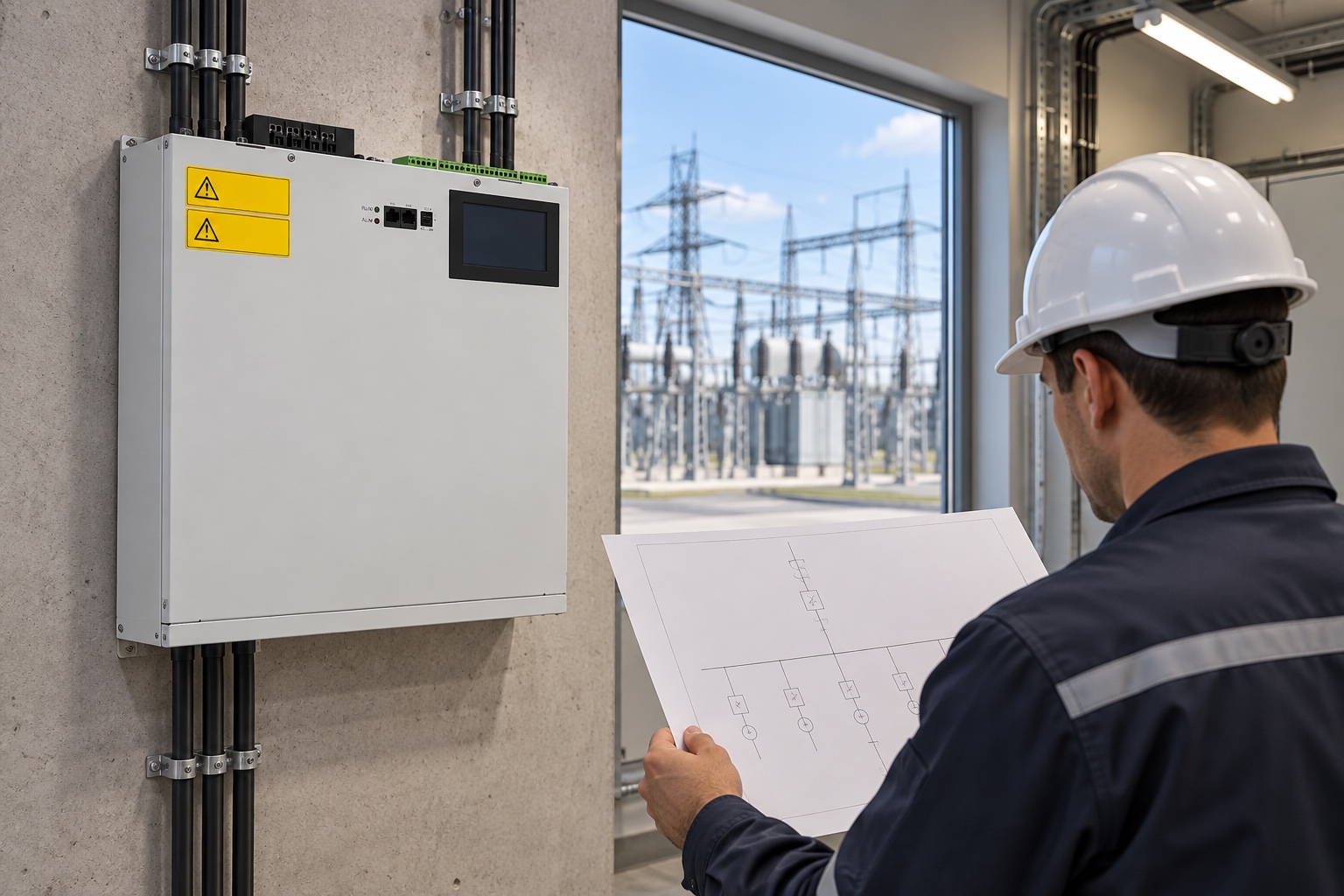
Image: contextual comparison between a product-referenced wall SVG and a grid substation; it is not a final one-line design.
Response and control objectives must be testable
“Fast response” is incomplete without a defined event, start and end points, tolerance band, sampling method and operating condition. State whether the goal is power-factor correction, voltage regulation, flicker reduction or reactive reserve. These objectives lead to different sensor locations and controller tuning.
A local SVG can measure a feeder and inject reactive current close to a fluctuating load. A larger SVC may regulate a bus using system-level voltage and reactive-power controls. The project should identify which controller owns the setpoint and how it coordinates with transformers, generators, capacitor banks and other compensators. Avoid two independent devices continually correcting each other.
La SVG reactive-current explanation covers the current-control concept. For any proposal, request response plots tied to the offered configuration and verify them during commissioning under a safe, representative test.
Harmonics, filters and resonance
An SVC design commonly treats harmonic filters and reactive branches as one system. Switching and thyristor operation influence the spectrum, and passive branches interact with network impedance. A converter-based SVG also produces a switching spectrum and operates in an existing harmonic environment. Neither should be declared “harmonic free.”
Provide background voltage distortion, current spectra by operating state, existing filters and capacitor banks, transformer data and known resonances. Require the supplier to state modeled cases and filter assumptions. If a plant also needs active harmonic filtering, decide whether that is a separate AHF function or part of a combined product, and reserve sufficient current for each function.
Installation and lifecycle scope
A modular SVG project may include rack or wall equipment, CTs, breakers, cabinet airflow, communications and low-voltage cabling. An SVC station can add reactors, capacitor/filter banks, thyristor valves, dedicated cooling, high-voltage switchgear, controls, foundations and fencing. Comparing only the electronic controller price would be meaningless.
For a low-voltage project, use the SVG installation and commissioning workflow to define integration ownership. Preserve before-and-after evidence with a consistent method such as the APF and SVG comparison procedure; neither page replaces a system-level SVC study.
For low-voltage assemblies, IEC 61439-1 provides general assembly rules. Higher-voltage or utility installations require the standards, grid codes and owner practices applicable to that project. Put these requirements in the RFQ rather than assuming they are included.
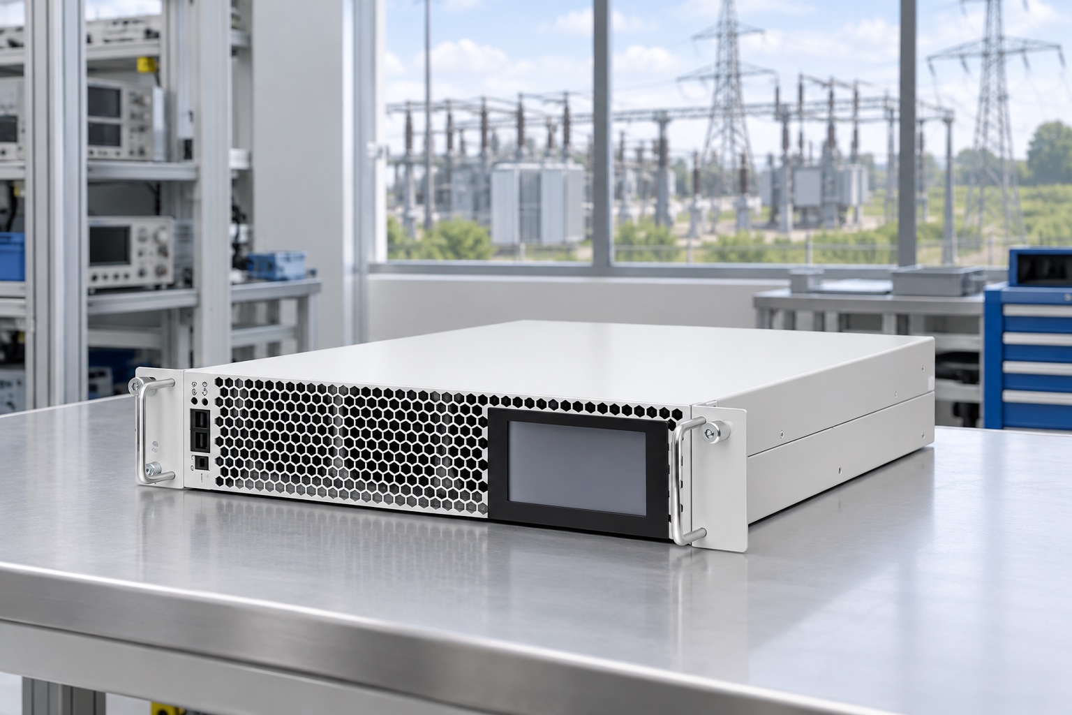
Image: product-referenced rack SVG in a low-voltage test setting; the outdoor substation is contextual and not an SVC design drawing.
Lifecycle evaluation should include losses, auxiliary cooling, planned inspections, filters, spares, software support, service response and outage strategy. Ask which components are field-replaceable and how a failed branch or module affects remaining capacity. Use written model-specific data in the financial comparison.
Decide by application, not by label
A plant with fast, local kvar swings and limited space may favor distributed modular SVGs. A network operator needing large bus-voltage support may require an engineered SVC or a utility-scale STATCOM. Between those extremes, connection voltage, system strength, duty cycle, site area, harmonic study, redundancy and owner experience determine the architecture.
Create a common basis of design: bus voltage, required range, voltage envelope, operating modes, response definition, harmonic limits, redundancy, availability, environmental conditions and acceptance tests. Request a deviation schedule from every bidder. A proposal that cannot map its offered system to those requirements is not ready for price comparison.
Study cases and acceptance records
The study scope should cover maximum and minimum load, credible generation patterns, normal and contingency network configurations, energization or branch switching, and the loss of one compensation element where redundancy is claimed. Examine bus voltage, reactive flow, equipment loading, harmonic response and control interaction. State the network model revision and assumptions so results can be updated when the system changes.
Factory tests verify the supplied controls and equipment against an agreed procedure; they do not prove site performance in an absent network. Site commissioning should confirm CT/PT polarity, scaling, protection, communication, cooling, alarms, limits and control modes before performance testing. Use synchronized records for bus voltage, reactive output, setpoint and relevant breaker or branch states.
Define the event used to demonstrate response and the permitted pre-event and post-event conditions. If the objective is voltage regulation, record the controlled bus. If the objective is plant power factor, record the agreed metering point. Archive raw traces, settings and the as-left configuration. These records become the baseline for maintenance and future expansion.
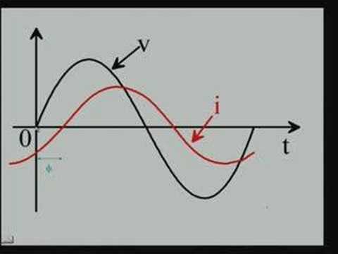
Neutral video: power factor and reactive power
NPTEL’s basic electrical technology lecture explains power factor, the electrical quantity both technologies are used to manage. It is background education, not a vendor comparison or project design.
Foire aux questions
Is an SVG the same as a STATCOM?
Many suppliers use SVG for converter-based equipment related to the STATCOM principle, especially at low voltage. The commercial name alone is insufficient; verify topology, voltage, capability curve and applicable standards.
Is an SVC always a high-voltage installation?
SVC technology is strongly associated with medium- and high-voltage systems, but project terminology varies. Define the actual branch architecture and connection voltage rather than relying on the name.
Which technology responds faster?
A converter-based design generally offers fast continuous current control, but a valid claim needs a defined test. Compare offered-system response under the same event, voltage, loading and tolerance criteria.
Can an SVG and SVC operate in the same network?
They can, but their voltage, reactive-power and harmonic controls must be coordinated. A system study should examine interaction across normal and contingency cases.
Selection outcome
Use a modular SVG when the measured problem is local, fast-changing reactive current within a suitable low-voltage installation. Evaluate an SVC when the duty is a larger engineered bus-compensation problem suited to thyristor-controlled branches. For both, require capability curves, study assumptions, a complete scope and a witnessed acceptance method.
Retain the approved study model and commissioning records for later system changes.