

batteries de condensateurs sont des assemblages de plusieurs unités de condensateurs de puissance connectés en série, en parallèle ou les deux afin que le groupe réponde à une tension nominale cible et à une puissance réactive (kvar) de sortie. Les usines connectent généralement cet assemblage en dérivation avec un jeu de barres ou une charge pour fournir de la puissance réactive locale et améliorer le facteur de puissance.
Ce guide aborde le rôle de l'usine, la façon dont le déphasage en avance compense les moteurs inductifs, les principaux types, les choix d'emplacement et le moment où les harmoniques font d'une batterie simple un mauvais premier choix. Pour les calculs de dimensionnement en kvar, consultez notre document séparé dimensionnement des batteries de condensateurs pour l'amélioration du facteur de puissance article au lieu de traiter cette page comme une calculatrice.
Qu'est-ce qu'une batterie de condensateurs
Une batterie de condensateurs n'est pas un simple boîtier doté de deux bornes : c'est un assemblage technique d'unités de condensateurs disposées de manière à ce que la capacité de tension et les kvar correspondent aux besoins de l'application.
Chaque unité stocke de l'énergie dans un champ électrique entre des conducteurs séparés par un diélectrique. Des chaînes en série augmentent la tension que l'ensemble peut supporter. Des branches en parallèle augmentent la puissance réactive totale.
La batterie terminée peut être installée sur un rack ouvert, dans une armoire métallique, sur un châssis tubulaire ou dans une armoire de compensation basse tension.
Dans le langage des plantes, vous entendrez également batterie de condensateurs en dérivation ou batterie de condensateurs de facteur de puissance. Un branchement en dérivation signifie que le banc est branché en parallèle avec la charge ou le jeu de barres — la configuration industrielle habituelle. Les bancs en série qui sont insérés directement sur un circuit de transport à longue distance résolvent un problème de réseau différent et restent en dehors de cette discussion sur les installations BT.

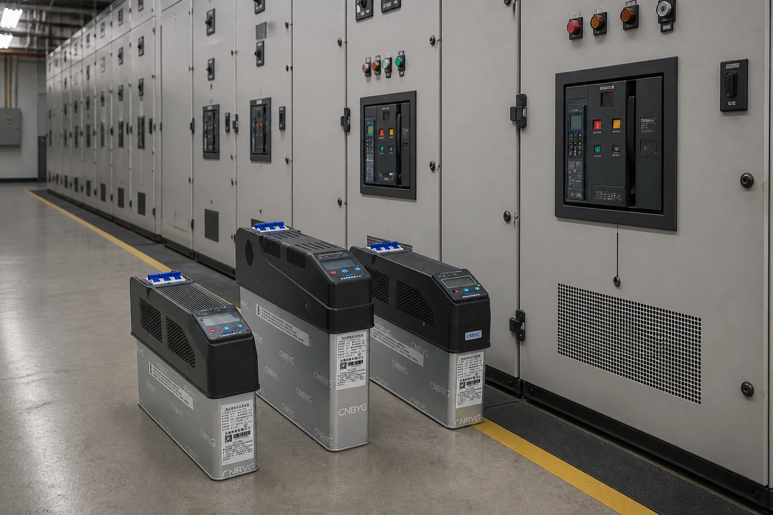
Le rôle des batteries de condensateurs dans le système électrique d'une usine
Les batteries de condensateurs sont présentes dans les usines principalement pour correction du facteur de puissance par batterie de condensateursils fournissent de la puissance réactive localement afin que les équipements inductifs ne tirent pas autant de courant en retard à travers les transformateurs, les câbles et les réseaux de distribution en amont.
Les moteurs, les transformateurs et de nombreux ballasts d'éclairage nécessitent un courant de magnétisation. Ce courant produit peu de travail mécanique ou thermique utile, mais il compte néanmoins dans la puissance apparente (kVA). Le facteur de puissance — la puissance réelle divisée par la puissance apparente — chute lorsque cette demande réactive inductive est élevée.
De nombreux services publics américains peuvent appliquer des frais supplémentaires lorsque le facteur de puissance du site descend en dessous d'environ 0,95. Même sans pénalité explicite sur la facture, le courant supplémentaire soumet tout de même les équipements de l'usine à des contraintes.
Lorsqu'une batterie de condensateurs correctement dimensionnée injecte un soutien réactif en amont à proximité de ces charges, le réseau et les transformateurs principaux de l'usine voient une composante réactive plus faible. Le courant dans les départements peut diminuer pour une même charge de processus en kilowatts, et la capacité libérée du transformateur devient disponible pour la croissance de la production.
Si vous avez toujours besoin de l'idée plus générale de la rémunération elle-même, commencez par qu'est-ce que la compensation de puissance réactive, puis revenez ici pour la vue de la banque en tant qu'équipement.
Comment les batteries de condensateurs fournissent de la puissance réactive
Les batteries de condensateurs fournissent de la puissance réactive en aspirant un courant capacitif qui compense le courant inductif requis par les charges inductives.
Sur un bus à courant alternatif, le courant d'un condensateur idéal est en avance d'environ quatre-vingt-dix degrés sur sa tension aux bornes. Le courant de magnétisation d'un moteur à induction est en retard par rapport à la tension. Placez le condensateur en dérivation avec l'alimentation du moteur ou un bus partagé et les deux courants réactifs s'annulent partiellement.
La véritable puissance continue de circuler vers l'arbre. L'échange réactif “ latéral ” se produit plus localement entre le moteur et le condensateur au lieu d'être acheminé depuis le générateur du réseau électrique.
Considérez la puissance réactive comme la portion de courant qui maintient les champs magnétiques actifs. La batterie devient un réservoir local pour cet échange. Les contrôleurs et les commutateurs décident du nombre d'étages de ce réservoir qui sont en service à mesure que la charge de l'usine change.
La sélection approfondie de kvar, les tables de $\tan\varphi$ et les feuilles de calcul du facteur de puissance cible doivent figurer dans le guide de dimensionnement en direct lié ci-dessus. Cette section verrouille uniquement le mécanisme afin que les choix ultérieurs de type et de risque aient du sens.
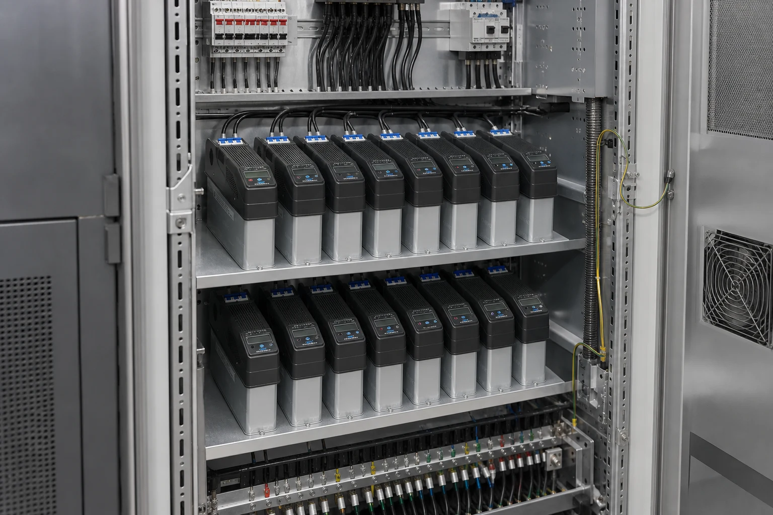
Principaux types de batteries de condensateurs en un coup d'œil
La plupart des discussions de projet classent les batteries de condensateurs selon leur mode de commande et la présence d'un accord d'harmoniques, et non par marque.
| Taper | Ce que vous obtenez | Coupe classique |
|---|---|---|
| Batterie de condensateurs fixe | Un bloc de kvar réglé qui reste alimenté chaque fois que le circuit est sous tension | Charge inductive stable qui oscille rarement |
| Batterie de condensateurs automatique | Plusieurs gradins commutés par un régulateur de facteur de puissance ou de kvar | Équipes, processus par lots ou profils de charge journaliers |
| batterie de condensateurs désaccordée | Échelons de condensateurs et réacteurs série qui abaissent la résonance en dessous des harmoniques courants | Installations avec des variateurs de fréquence, des redresseurs ou d'autres charges non linéaires |
Les étiquettes d'emballage sur les projets de services publics ou à moyenne tension — racks ouverts, ensembles sous enveloppe métallique, structures sur poteau ou remorques mobiles — décrivent l'enveloppe et le montage, et non une fonction électrique différente. Les sites industriels à basse tension répondent plus souvent au même principe que les gradateurs montés en armoire avec des contacteurs ou des commutateurs à semi-conducteurs, parfois intégrés dans condensateur intelligent modules.
Le type de protection (constructions à fusibles internes, à fusibles externes ou sans fusibles sur les racks MT) a une importance pour la maintenance et le comportement en cas de défaut. Il ne modifie pas la première question que se pose le lecteur : s'agit-il d'une batterie de condensateurs fixe, d'une batterie de condensateurs automatique ou d'une batterie de condensateurs désaccordée ?
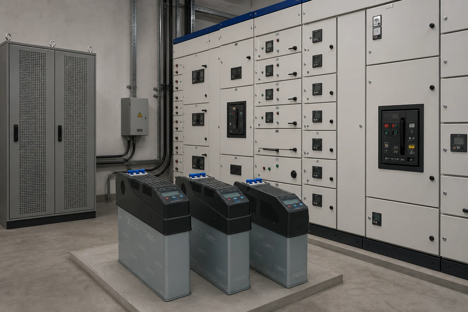
Où se trouvent les batteries de condensateurs dans une usine
Les batteries de condensateurs sont placées là où le problème réactif est suffisamment concentré pour justifier le matériel, et où la commutation ne surprendra pas les équipements sensibles.
| Placement | Idée de connexion | Force | Attention |
|---|---|---|---|
| Centralisé | Près du tableau général basse tension ou du jeu de barres BT principal | Un seul paquet, un seul contrôleur, facile à voir sur une seule ligne | Peut manquer les centres de charge distants ; des pas plus importants peuvent faire osciller tout le bus |
| Groupe / décentralisé | Aux tableaux de distribution alimentant des groupes de moteurs | Rapproche la demande réactive des charges qui la créent | Plus de panneaux à entretenir et à coordonner |
| Local | Sur un grand compresseur, un broyeur ou une autre machine inductive dominante | Corrige le pire contrevenant avec un trafic amont minimal | De nombreuses petites banques augmentent les coûts si chaque moteur a le sien |
Les équipes d'achats commencent souvent par la centralisation parce que le devis semble simple. Les ingénieurs méthodes préfèrent parfois des bancs locaux sur les plus grands moteurs pour que le jeu de barres principal ne transporte jamais ce courant de magnétisation.
Les installations mixtes utilisent les deux : un banc principal modeste ainsi qu'une correction locale sur quelques machines lourdes. La bonne cartographie dépend des profils de charge mesurés, et non d'un slogan universel.
Limites, harmoniques et pourquoi une banque est le mauvais premier choix
Une batterie de condensateurs peut provoquer un effet indésirable lors de la commutation de régimes transitoires ou en parallèle résonance harmonique avec des charges non linéaires qui surchargent le diélectrique, les fusibles et les variateurs voisins.
La mise sous tension d'une batterie de condensateurs n'est pas un événement bénin. Des courants d'appel et des perturbations de tension apparaissent lorsque la capacité rencontre l'inductance du réseau. La manœuvre dos à dos — la fermeture d'une batterie alors qu'une autre est déjà en service sur le même jeu de barres — peut s'avérer encore plus sévère.
Des contrôleurs, une impédance de pré-insertion ou une commutation au passage par zéro existent spécifiquement pour maîtriser cette contrainte.
Les harmoniques modifient encore l'histoire. Les charges non linéaires (variateurs de fréquence, postes à souder, entrées d'onduleurs) injectent des courants à des multiples de 60 Hz. L'impédance capacitive diminue à mesure que la fréquence augmente, de sorte que ces courants préfèrent la batterie de condensateurs.
Si la batterie de condensateurs et l'inductance d'alimentation résonnent près d'une harmonique caractéristique (souvent la 5e ou la 7e), la distorsion de tension peut augmenter, les fusibles peuvent surchauffer et les condensateurs peuvent tomber en panne prématurément.
Du terrain : Les discussions sur les forums professionnels concernant les équipements de correction automatique du facteur de puissance font état de bourdonnements bruyants, de surchauffes de réacteurs ou de condensateurs et de fusibles grillés — parfois suffisamment graves pour que les exploitants laissent l'équipement éteint “ par peur d'incendie ”. Ce langage constitue un avertissement concernant la résonance et les charges non linéaires, et non une raison d'abandonner totalement la correction du facteur de puissance.
Important : Ne considérez pas une batterie de condensateurs simple et non désaccordée comme inoffensive sur un réseau fortement perturbé par des variateurs de vitesse sous prétexte que le facteur de puissance de déplacement semble faible sur un récapitulatif de facturation. Mesurez la distorsion de tension et de courant, étudiez le risque de résonance et envisagez un réacteur en série avec les condensateurs — ou une autre technologie de puissance réactive — avant d'ajouter des échelons. Condensateurs harmoniques et de correction du facteur de puissance IPQDF
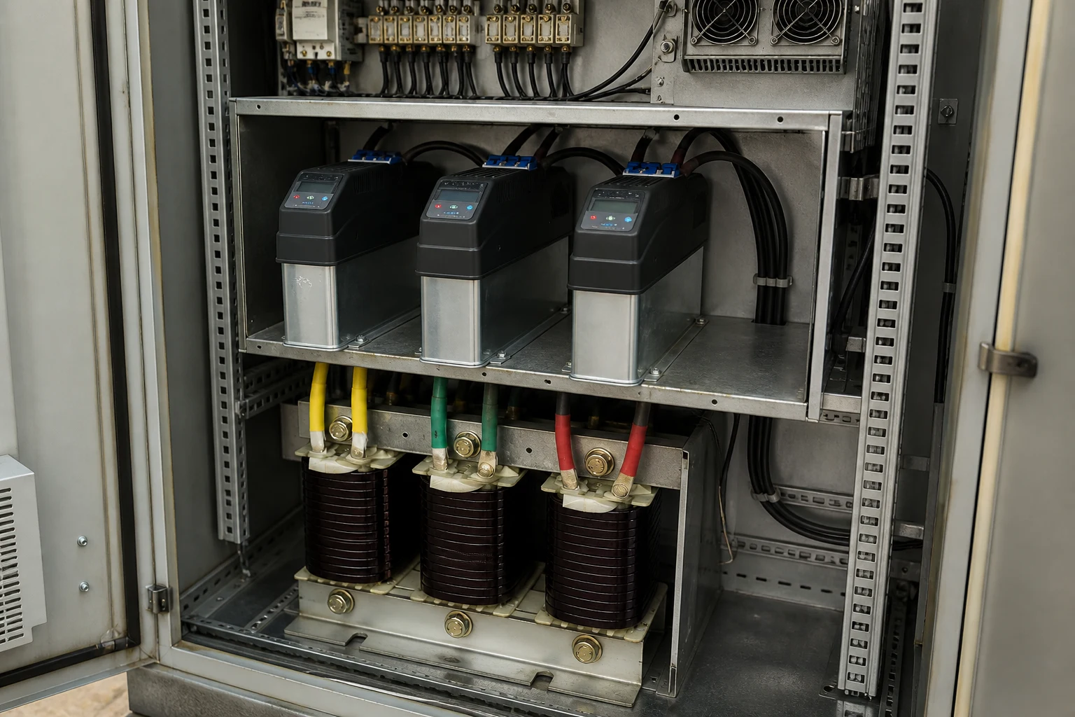
Lorsque les charges oscillent rapidement, que des puissances réactives bidirectionnelles sont nécessaires ou que les spectres d'harmoniques ne cessent de varier, des options à base d'électronique de puissance telles qu'un compensateur statique d'énergie réactive (SVG) peuvent s'avérer plus adaptées qu'un échelon de condensateurs supplémentaire. La batterie reste un outil robuste et économique pour une demande réactive inductive constante dans un réseau suffisamment propre ; elle ne constitue pas une solution universelle par défaut.
Sélection du matériel pour condensateurs BT et étapes suivantes
Pour les ensembles d'installations basse tension, commencez par des blocs de condensateurs en dérivation éprouvés et une commutation contrôlée, puis ouvrez l'article sur le dimensionnement avant de figer les totaux de kvar.
Le concentrateur de compensateur de puissance réactive de CNBYG regroupe les éléments qui apparaissent habituellement ensemble dans une batterie BT : unités de condensateurs shunt, modules de condensateurs intelligents, réacteurs en série, régulateurs et accessoires de commutation. Le Condensateurs intelligents de la série BY81 combinez la mesure et le contrôle avec une commutation synchrone au passage par zéro pour que les étages puissent s'enclencher sans l'appel de courant incontrôlé d'une fermeture brutale de contacteur naïf.
Condensateur de dérivation à autorégénération BSMJ Les unités fournissent les composants en film métallisé que de nombreuses armoires utilisent encore comme cœur kvar. Lorsque les harmoniques nécessitent un désaccord, associez les condensateurs à une réactance série telle que le Série CKSG.
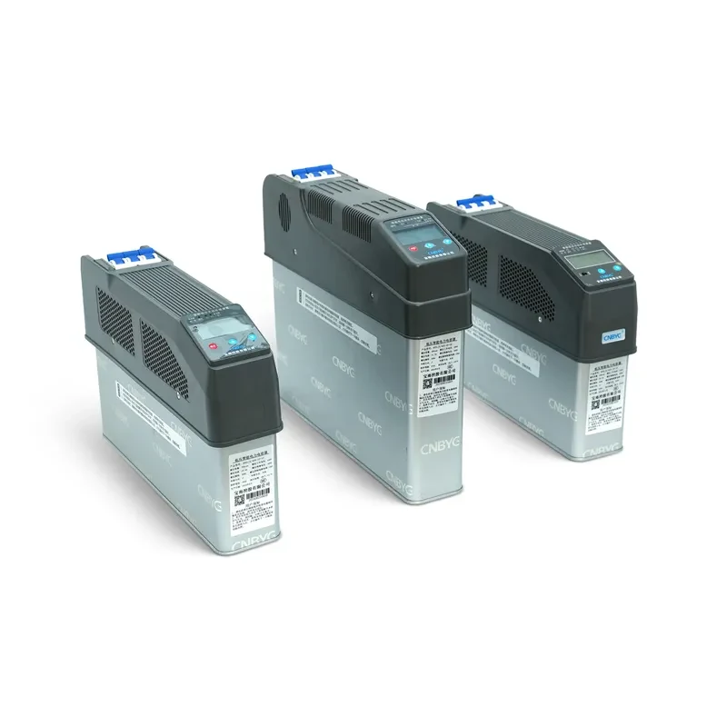
Aucune de ces pages de produits ne remplace une mesure sur site ou la feuille de calcul kvar. Lorsque vous êtes prêt pour les chiffres, continuez vers dimensionnement des batteries de condensateurs pour l'amélioration du facteur de puissance. Utilisez cette page de définition pour garder le vocabulaire, les choix de placement et les limites harmoniques clairs pendant que ce travail de dimensionnement se poursuit.
FAQ
Quelle est la différence entre un condensateur et une batterie de condensateurs ?
Un condensateur de puissance unique est une unité scellée dotée d'une tension nominale et d'une puissance réactive en kvar. Une batterie de condensateurs est l'assemblage de plusieurs unités — ainsi que du châssis, du boîtier, des fusibles, des interrupteurs et souvent d'un contrôleur — câblées de manière à ce que l'ensemble réponde aux besoins totaux de l'application en matière de tension et de kvar.
Pourquoi les usines installent-elles des batteries de condensateurs ?
Les usines installent des batteries de condensateurs pour fournir de la puissance réactive locale aux charges inductives, améliorer le facteur de puissance, réduire le courant inutile dans les lignes d'alimentation et les transformateurs, et — lorsque des tarifs s'appliquent — éviter les pénalités pour faible facteur de puissance que de nombreux services publics peuvent appliquer en dessous d'environ 0,95.
Les batteries de condensateurs sont-elles la même chose que la correction du facteur de puissance ?
Une batterie de condensateurs est l'un des matériels les plus couramment utilisés pour la correction du facteur de puissance en dérivation, mais la “ correction du facteur de puissance ” est l'objectif du système. La correction peut également impliquer des pratiques d'exploitation, d'autres équipements ou un support réactif à base d'électronique. Voir aussi qu'est-ce que la compensation de puissance réactive.
Fixe ou automatique — lequel s'adapte aux charges de moteur variables ?
Une batterie de condensateurs fixe convient à une demande inductive relativement stable. Une batterie de condensateurs automatique ajoute et retire des échelons de kvar à mesure que la charge de production varie, de sorte que le site ne reste ni sur-compensé ni sous-compensé d'une équipe de travail à l'autre.
Est-ce qu'une batterie de condensateurs peut créer des problèmes d'harmoniques ?
Oui. Avec l'inductance du réseau, une batterie de condensateurs peut former une résonance harmonique parallèle près d'une fréquence harmonique.
Dans les usines riches en variateurs de vitesse, cela se manifeste par une surchauffe, des déclencheurs de fusibles, du bruit ou une distorsion croissante. Une batterie de condensateurs désaccordée, des filtres ou des technologies de réactivité alternatives permettent de contrer ce risque après mesure.
Où la banque doit-elle se connecter dans une usine ?
Centralisés au tableau principal, regroupés dans les tableaux de distribution, ou locaux sur les grandes machines constituent les trois schémas classiques. Choisissez en fonction de l'endroit où se concentre la demande réactive et de l'amplitude de variation de la tension du bus que vous pouvez tolérer lors des commutations.
Comment calculer la taille des kvar ?
Utilisez la puissance réelle mesurée et les angles actuels par rapport aux angles de facteur de puissance cibles — ou une feuille de calcul équivalente — sur notre dimensionnement des batteries de condensateurs page. Cet article de définition ne réaffirme intentionnellement pas ces mathématiques.
Quand dois-je envisager un condensateur intelligent ou une bobine de réactance antirésonnante ?
Pensez à un module de condensateur intelligent lorsque vous avez besoin d'une détection intégrée et d'une commutation contrôlée au passage par zéro dans un tableau BT. Ajoutez une réactance en série lorsque les mesures d'harmoniques révèlent un risque de résonance avec des étages de condensateurs simples. Examinez les options de compensateur de puissance réactive plateforme avant le gel d'une nomenclature.
Références
- Département de l'Énergie des États-Unis — Réduction du coût du facteur de puissance
- IEEE Technology Navigator — Batteries de condensateurs
- Technologie électrique — Caractéristiques et applications des batteries de condensateurs
- IEEE SA — Guide IEEE 1036-2020 pour l'application des condensateurs de puissance shunt
- IPQDF — Harmoniques et condensateurs de facteur de puissance