How to Correct Low Power Factor Without Overcompensation
How to Correct Low Power Factor Without Overcompensation
Correct low power factor without overcompensation by defining the measurement point, separating inductive and capacitive conditions, checking CT polarity, and applying only the reactive current that the load actually needs. A high power-factor number is not automatically a good result if the plant becomes leading at light load, capacitor steps hunt, generator voltage becomes unstable or the SVG is forced to chase the wrong boundary.
Itu Halaman produk CNBYG SVG provides product context, but the target, current limit and protection settings must be selected from measured site conditions. The safe objective is a stable and repeatable operating range, not the largest possible displayed value.
Define what “low” means
Power factor can be reported as displacement power factor, true power factor or a utility-specific billing value. Confirm whether harmonics are included and where the meter is installed. A motor feeder, main incomer and generator terminal can show different values at the same instant. Write the target, sign convention, averaging interval and load state before changing compensation.
Collect kW, kvar, voltage, current, frequency, THD and individual harmonic orders during light load, normal production and peak production. Note fixed capacitors, APFC stages, generators, UPS units and VFDs. Overcompensation often appears when production stops but capacitive devices remain connected.

Diagnostic table
Use the table to separate measurement, capacity and coordination causes.
| Pengamatan | Wilayah yang mungkin | Pemeriksaan pertama |
|---|---|---|
| PF is low at every load | Measurement, sizing or a persistent inductive load. | CT polarity, boundary, kvar and available current. |
| PF becomes leading at light load | Fixed capacitors, cable capacitance or generator operation. | Minimum-load rule and other compensation devices. |
| PF changes sign unexpectedly | CT/phase reference or controller sign convention. | Phase sequence, polarity and voltage reference. |
| PF is good at the SVG but poor at the incomer | Different measurement boundary or downstream source. | Compare synchronized meters and CT locations. |
| PF misses target only at peak load | Insufficient current, low voltage or shared harmonic duty. | Output current, voltage and capability curve. |
| PF hunts around the target | Competing controllers, delay or an unstable setpoint. | APFC/SVG priority, deadband and switching sequence. |
| PF looks better but THD worsens | Shared current limit or a resonance interaction. | Harmonic spectrum and enabled priorities. |
Verify CTs and the reference boundary
Check CT ratio, phase, polarity, location, burden and shorting arrangement. Confirm the SVG voltage reference uses the same phase order and boundary. Use an independent analyzer to compare current direction and signed kvar. Do not adjust the target until the measurement chain is proven.
Itu Panduan kompensasi arus reactive-current SVG explains why a correct unit can appear wrong when its CT boundary or sign convention differs from the plant meter. Save the raw trace and a marked one-line drawing.
Apply only the required reactive current
Calculate the reactive current needed for the target at the actual voltage and kW. Add margin for variation, but do not use an arbitrary oversized target. At light load, the same fixed capacitor kvar can become a leading condition. If an SVG is used, define a minimum-load rule or a target band that prevents unnecessary oscillation.
Itu Panduan tegangan grid dan kapasitas SVG explains why lower voltage can require more current for the same kvar. Check the converter’s capability curve before raising a limit. A target that is physically unavailable should be reported as a capacity issue, not hidden by a more aggressive setting.
Coordinate other compensation devices
List every device that can change reactive current: fixed capacitors, APFC steps, synchronous machines, generators, UPS systems and other SVG or SVC equipment. Decide which device handles base kvar, which responds quickly and which is blocked at minimum load. Add interlocks for generator mode if the plant requires them.
Do not allow two controllers to chase the same error with similar gain and delay. Define deadband, delay, priority and fallback. If communication is lost, the equipment should move to an approved local behavior rather than an unknown target.

Corrective sequence
- Confirm the billing or operational definition of power factor.
- Mark the electrical measurement point and verify CT/voltage references.
- Compare plant meter, SVG display and independent analyzer under the same load.
- Separate inductive demand from fixed capacitive or harmonic effects.
- Check voltage, available current, temperature and protection limits.
- Review APFC, generator and other compensator priorities.
- Set a documented target band and minimum-load behavior.
- Test light-load, normal-load, peak-load and transition cases.
- Save old and new settings, traces, alarms and acceptance results.
Acceptance without overcorrection
Acceptance should include the lowest normal load, not only the production peak. Record signed kvar, PF, voltage, current, THD and the status of capacitor steps. Verify that the source does not become leading beyond the agreed limit and that the SVG does not repeatedly enter and leave a current limit.
If the site uses a generator, test transfer and return only under an approved procedure. Generator voltage regulation and minimum loading can change the safe compensation range. The result should state which devices were enabled, which were blocked and what fallback applied.
For general power-quality measurement method context, IEC 61000-4-30 is listed in the IEC catalogue. Use the manufacturer’s instructions for protective limits and site safety.
A repeatable sizing method
Start with the measured active power at the correction point and the power-factor target agreed with the utility or process owner. Convert the difference into a reactive requirement using the same sign convention as the meter. Then check the lowest normal voltage, because the current required for that kvar rises as voltage falls. Add a documented margin for load variation rather than an unexplained percentage.
Next, subtract or model the reactive contribution of fixed capacitors, transformer magnetizing current and other compensators. A capacitor bank that is correct at peak load can be excessive when the process stops. Define the minimum load at which each step may remain connected. If a generator operates in parallel, include its voltage-control and minimum-loading rules in the study.
For an SVG, compare the calculated current with the continuous and short-time capability at the measured voltage and ambient. If harmonic or unbalance compensation is enabled, reserve current for those functions. Write what the controller does at saturation: reduce harmonic priority, relax the PF target, or alarm and hold. The operator should not have to guess from a display.
Validate the method with a controlled load change. Record the old settings, new settings, voltage, kW, kvar, PF, THD, output current, capacitor state and alarms before and after the change. Repeat at light, normal and peak load. If the plant cannot reproduce the same load, document the limitation and use a synchronized time series instead of claiming a full acceptance result.
This approach also helps explain a disappointing result. If the requested target is beyond the available current, the solution may be a larger unit, a different measurement boundary or a change to other compensation equipment. If the result is wrong only at light load, the solution is usually coordination or a minimum-load rule, not more converter capacity.
Keep a distinction between correction and optimization. Correction restores the agreed operating band; optimization may change priorities, delay, deadband or the order in which capacitor stages respond. Make one controlled change at a time and allow the plant to reach steady state before judging it. If the source meter, SVG display and independent analyzer disagree, retain all three records and resolve the boundary before tuning. That discipline avoids a cycle in which one shift improves a number while another shift inherits a leading condition. The SVG commissioning guide can be used to document the retest.
Include the responsible person, change reason and rollback setting in the record. A clear rollback is especially important when production cannot be interrupted for a long observation period.
Keep the acceptance decision tied to the operating range, not a single best-case snapshot. State the minimum and maximum load observed, the voltage range, the status of capacitor stages and the period used for averaging. This makes the correction auditable when another shift or season produces a different reactive demand.
Pertanyaan yang sering diajukan
Is a power factor of 1.00 always the best target?
Not necessarily. A stable band slightly below unity may avoid leading operation, hunting and unnecessary current. The correct target depends on the utility rule and the plant’s operating envelope.
Why does PF become leading after a shift ends?
Fixed capacitors, cable capacitance or generator conditions may remain while inductive load falls. Use a minimum-load rule and coordinate switching devices.
Can changing the SVG gain fix overcorrection?
Only after CTs, boundary, target and other devices are verified. Gain cannot correct a reversed CT or an oversized fixed capacitor.
What evidence proves the correction is safe?
Keep synchronized readings across light, normal and peak load, plus settings, alarm history, capacitor status, voltage, ambient and the signed acceptance decision.
Kesimpulan
Low power factor should be corrected with measured current and a defined boundary, not with the most aggressive setpoint. Verify CTs, calculate the real reactive requirement, coordinate other devices and test light-load leading conditions. A stable target band with documented fallback is safer and more useful than a perfect number that cannot be repeated.
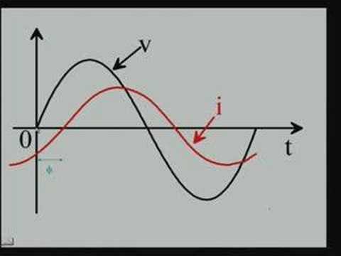
Video netral: latar belakang faktor daya
The NPTEL lecture below provides neutral background on power factor. It is educational context, not a troubleshooting or product recommendation.