APFC Controller Alarm Codes and Troubleshooting
APFC controller troubleshooting should begin with the exact alarm message, controller model and operating state. Alarm codes are manufacturer-specific: a code from one manual cannot safely be applied to another device. Save the message and event time, identify what protection action occurred, then separate measurement, supply, stage-output, thermal and harmonic problems. Resetting an alarm without addressing its cause can hide an unresolved fault. If there is damaged insulation, overheating, abnormal noise or repeated protection operation, follow the plant’s procedure for taking the affected equipment out of service.
This guide provides a diagnostic framework for capacitor-compensation controllers. It deliberately does not invent a universal JKW alarm-code list. Use the exact product manual alongside automatic power-factor-controller settings.
Preserve the first useful evidence
Before clearing an alarm, record its displayed text or code, timestamp, active stages, operating mode and load condition. Photograph the display from a safe position if appropriate. Retain any event log or communication record. An alarm that appears only during a stage transition may require different investigation from one present immediately after controller power-up.
Record what the controller actually did. It may have blocked new connections, disconnected one stage, disconnected all stages or issued only a warning. These behaviors are not interchangeable. Operators need to know which equipment remains active and whether an automatic reset or restart is configured.
Include recent changes: replacement capacitors, CT work, controller replacement, new drives, ventilation maintenance or a changed target. Timing can help form a hypothesis, but it does not prove causation. Keep the earlier configuration so a later review can compare settings rather than relying on memory.
Obtain the correct manual and identify the alarm meaning
Use the controller’s full model designation and the relevant manual or firmware revision. A series may contain variants with different input ratings, output counts and features. Confirm that the manual’s terminal diagram and menu descriptions match the installed unit.
Translate the alarm into its documented condition and action. Determine whether it refers to supply voltage, measured current, insufficient compensation, stage response, temperature, harmonic conditions or communication. Do not infer a numeric threshold from the alarm name. Check the configured setting and any factory or project requirement for the exact equipment.
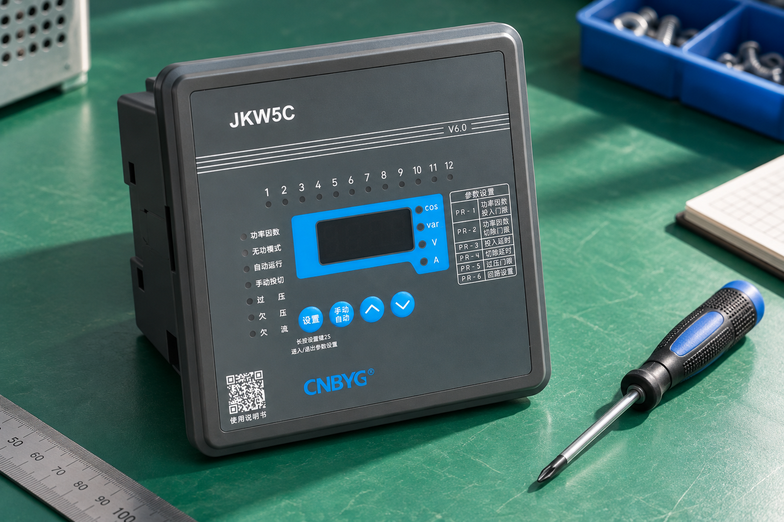
For CNBYG JKW reactive-power controllers, provide a nameplate photograph and the actual message when requesting support. Ask for the model-specific interpretation rather than assuming a generic internet list applies.
A practical alarm-group triage table
| Alarm group | Evidence to collect | First diagnostic distinction |
|---|---|---|
| Supply or voltage | Actual measurement point, voltage readings and event timing | Is the supply abnormal, or is the measurement/configuration wrong? |
| Current or CT signal | CT ratings, input compatibility, location and load | Is the current genuinely small or absent, or is the measurement chain faulty? |
| Insufficient correction | Reactive demand, connected stages and available capacity | Is capacity insufficient, a stage unavailable or the CT unable to see correction? |
| Stage response | Command log, switching state and measured branch output | Did the stage fail to operate, or did the controller fail to measure its effect? |
| Suhu | Sensor type, location, enclosure ambient and cooling | Is the assembly overheating, or is sensor/configuration interpretation wrong? |
| Harmonic or power quality | Instrument definitions and voltage/current spectra | Is measured duty outside the design, or are unrelated metrics being compared? |
| Communication | Address, protocol, wiring and local controller operation | Is remote reporting lost while local compensation still works? |
The groups are a troubleshooting aid, not a product code table. The electricity authority’s APFC specification illustrates why measurement, protection and control functions need to be documented together. Confirm the installed model’s actual implementation.
Investigate supply-voltage alarms at the correct point
Compare the controller’s voltage quantity with the exact measurement scheme. A phase-to-phase input and a phase-to-neutral input represent different quantities. Confirm any configured nominal value or scaling before diagnosing an overvoltage or undervoltage condition.
Correlate the event with motor starts, source changes, bus-coupler operation and production cycles. A short event may require suitable logging to capture; an occasional handheld reading taken much later may not represent the alarm condition. Record instrument location and timing so the comparison is meaningful.
Do not widen thresholds simply to make the alarm disappear. The permitted range should come from the equipment and project requirements. If the supply genuinely exceeds those conditions, address the supply problem or review the equipment design with the responsible engineer.
Investigate CT and current-signal alarms safely
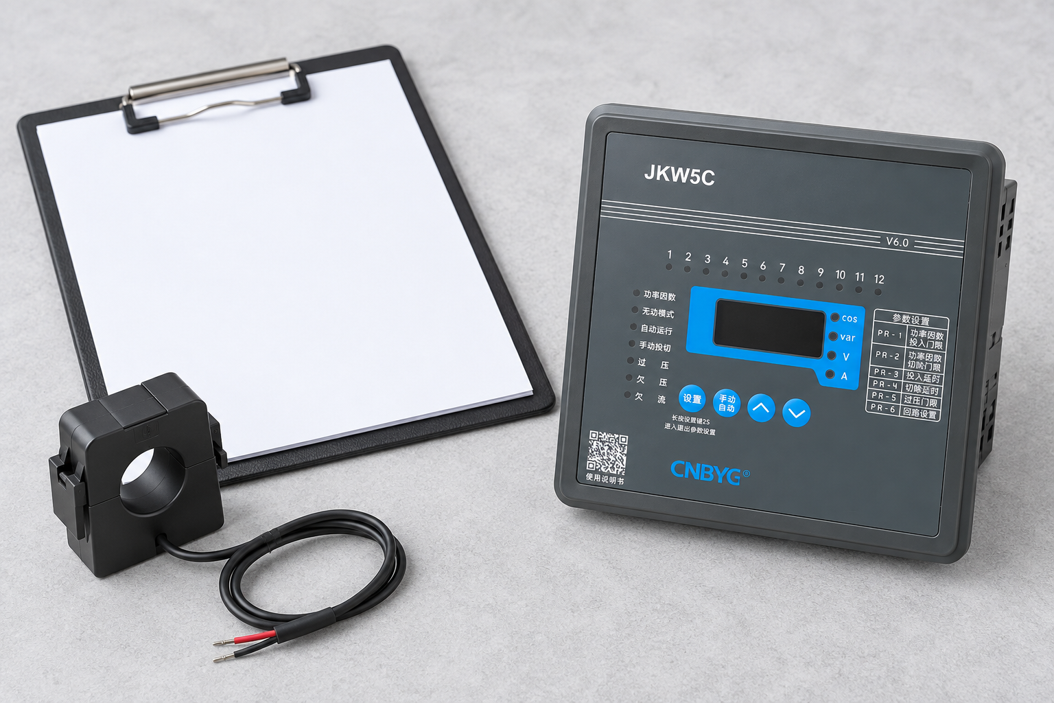
Check the physical CT rating, connected secondary tap and controller input capability. Confirm the menu convention used for scaling. A controller expecting primary amperes may be misconfigured if a mathematical ratio was entered, and a physical 1 A or 5 A secondary must be compatible with the specified input.
Consider light-load operation separately. A very small secondary signal can affect measurement or automatic stage learning without indicating a broken controller. Review the CT’s operating range and the device’s stated minimum signal requirements. Do not select an arbitrary new ratio merely to suppress a warning.
Physical CT work requires the approved qualified-person procedure. The California CT-secondary rule addresses the open-secondary hazard. Use APFC CT-ratio setup to organize the evidence; do not disconnect live secondary conductors as an informal test.
Separate insufficient capacity from failed stage output
An insufficient-compensation alarm can reflect demand beyond the bank’s available output, but it can also reflect unavailable stages, a wrong sequence or a CT location that excludes the correction response. Compare reactive demand with the actual net stage outputs at operating voltage and the stages genuinely available for connection.
Check controller commands against the switching-device state and measured branch output using the approved commissioning method. A commanded output does not prove a contactor closed, and a closed contactor does not prove that the capacitor branch supplies the expected kvar. A fuse or capacitor problem can leave a stage electrically ineffective.
Do not add more capacity before identifying missing existing output. Review the stage drawing, protection history and replacement records. If the bank genuinely lacks sufficient range or resolution, APFC step selection helps separate total capacity from minimum-stage control limitations.
Treat thermal alarms as evidence, not a setting inconvenience
Identify the sensor and what it measures. A winding sensor, core-mounted sensor and cabinet-air sensor have different meanings. Record the actual location, sensor type and configured action. An apparent mismatch may arise from comparing a sensor reading with an infrared surface measurement that represents another location.
Inspect ventilation, fans, blocked filters and nearby heat sources during the appropriate safe condition. Compare current and harmonic loading as well as enclosure ambient. A thermal issue can result from the interaction of electrical losses and inadequate cooling rather than one isolated defect.
Do not raise a threshold because the reactor’s insulation class appears high. The permitted operating conditions and protection setting belong to the complete assembly. If overheating accompanies discoloration, damaged insulation or repeated trips, follow the equipment shutdown procedure and obtain supplier review.
Investigate harmonic alarms with compatible measurements
Determine whether the alarm responds to voltage THD, current distortion, a particular harmonic or another model-specific quantity. The controller and reference analyzer may use different definitions or measurement bandwidths. Compare like quantities at the same operating point rather than treating every percentage as equivalent.
Capacitor-stage switching can change network conditions. Correlate events with stage combinations and nonlinear-load operation, and retain the harmonic spectrum. A single average reading can miss the condition that triggered protection. The bank’s intended harmonic duty and reactor matching should be reviewed if events recur.
Adding capacitor stages does not automatically remove current distortion. The OpenStax AC-power discussion explains the basic sinusoidal quantities, but a distorted-waveform problem requires an appropriate power-quality assessment and equipment response.
Distinguish communication failure from compensation failure
A remote monitoring system may lose data while the local controller continues operating. Check local display and stage behavior before declaring the compensation system unavailable. Conversely, a communication link that works does not prove that measurement or stage operation is correct.
Record the configured address, protocol settings, wiring arrangement and any recent changes to gateways or polling software. Follow the actual communication manual rather than changing several parameters at random. Preserve local operation during diagnosis unless the approved procedure requires shutdown.
Define what the operator should do when remote data is stale. A monitoring screen should not continue presenting old measurements as current. The maintenance record should state whether the issue affects remote reporting, local control or both.
Reset only after the documented conditions are satisfied
Use the manual’s reset and restart procedure after resolving the verified cause. Confirm whether a reset reconnects stages automatically and whether reconnection intervals still apply. Ensure personnel and equipment are ready for the actual action, not merely the disappearance of an alarm icon.
Repeat the relevant test under representative conditions. Record whether the alarm recurs, whether all required stages are available and whether protection functions behave as intended. A controller that remains quiet because the affected stage is disabled has not necessarily been restored to full service.
Save the fault, evidence, correction and verification in one service record. If the cause is unresolved, state that explicitly and retain the safe operating arrangement approved for the site. Repeated resets without diagnosis make the next investigation harder and can increase equipment stress.
Further learning
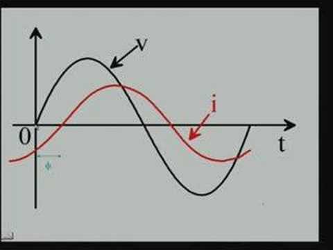
Watch Lecture – 15 Power Factor by nptelhrd
The NPTEL lecture explains power factor and reactive compensation. It is useful background for interpreting demand and correction, while the device manual supplies actual alarm meanings and actions.
Pertanyaan yang sering diajukan
Are APFC alarm codes universal?
No. Codes, thresholds and protective actions are model-specific. Match the installed controller and manual revision before using a code description.
Does an insufficient-compensation alarm mean a larger bank is needed?
Not necessarily. Verify available stages, actual branch output, measurement location and configuration first. Existing capacity may be unavailable or incorrectly observed.
Should a repeated thermal alarm be cleared by raising its threshold?
No. Investigate cooling, electrical loading, sensor interpretation and the assembly’s documented limits. Threshold changes require an approved engineering basis.
What should be sent with a support request?
Provide model identification, exact message, timestamp, load and stage states, configured values, wiring reference, measurements and recent changes. Include what protection action occurred and what has already been verified.