Peralihan Bank Kapasitor Sirkular vs Linear
Circular versus linear capacitor switching describes how a power factor controller chooses the next eligible capacitor stage, rather than how quickly a switch closes. Linear operation commonly follows a fixed stage order; circular operation rotates the duty among interchangeable stages. Rotation can distribute operations more evenly, but only when the stages have compatible ratings and the controller explicitly supports that arrangement. Neither mode overrides discharge time, protection, or the required reactive power. Choose the sequence from the actual stage layout, load behavior, and controller manual, then verify the result with recorded stage operations instead of assuming that a menu name guarantees correct performance.
What the two sequence names mean
A fixed sequence makes the relationship between output number and stage order easy to follow. An installation may bring in the first available stage, then the next stage, as reactive demand increases. When demand falls, the controller removes stages according to its documented algorithm. Some controllers use a reverse removal order, while others implement their own selection rules. The word linear alone does not establish the removal sequence, so an acceptance test must cover both rising and falling demand.
Circular switching rotates the starting point or the next selected output across a group of suitable stages. If three identical stages satisfy the same demand, the controller can alternate which one performs that duty. The aim is to avoid always assigning the earliest operations to one physical stage. Controllers may call this rotational, cyclic, or equal-duty operation. Those labels are useful clues, but the operating instructions determine whether the function rotates by order, elapsed operation, or another criterion.
Itu CNBYG JKW-series reactive power controller is a relevant physical controller reference. Its appearance does not prove that every variant offers either sequence. Obtain the manual and ordering specification for the installed model before promising a particular algorithm. The discussion below concerns a commissioning method, not undocumented firmware capabilities.
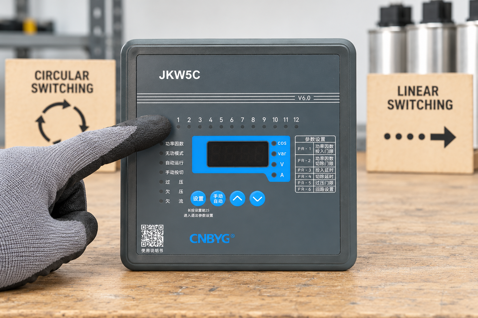
Separate selection order from switching hardware
The controller issues a request; the switching device connects or disconnects the capacitor branch. A contactor, composite switch, or appropriately specified semiconductor switch has its own operating limits. Changing the controller sequence does not change those limits or make a mechanical contactor suitable for rapid cycling.
Similarly, a circular sequence does not mean that several charged capacitors may be reconnected immediately. An unavailable stage must remain unavailable until its specified discharge and reconnection conditions have been satisfied. If the controller cannot track those conditions individually, the system designer must provide an appropriate arrangement. Read the related Panduan penundaan switching kapasitor before adjusting sequence settings.
A useful way to discuss the system is to separate three decisions: how much reactive power is needed, which stage combination supplies it, and which eligible physical stage supplies each interchangeable portion. Sequence is primarily the third decision. Confusing these decisions can produce a bank that alternates outputs neatly while still overcompensating the load.
Match the sequence to the stage ratings
Equal-sized stages are the simplest case for rotation. When each stage supplies approximately the same usable reactive power under the operating conditions, substitution has little effect on the total commanded compensation. The controller still needs to exclude a stage that is isolated, alarmed, or waiting for discharge. Stage age and measured performance also matter: two nominally identical units may no longer supply equal output.
Unequal stages require additional care. A fixed sequence can represent a designed progression, but it may miss useful intermediate combinations if the algorithm simply adds outputs in numerical order. A controller with intelligent combination selection may support unequal ratings without relying on a fixed progression. That is a separate capability and should be verified directly. Do not rotate a small trimming stage with a large bulk stage merely because both are connected to output relays.
Itu controller step selection guide explains the distinction between the number of available outputs and the compensation resolution. Use that distinction here: twelve outputs do not necessarily represent twelve equal stages, and an unused output is not an eligible capacitor branch.
A comparison table for commissioning decisions
The following table is a qualitative engineering checklist, not a statement of features available on any specific CNBYG controller. Electrical work and testing must follow the installed equipment instructions and the isolation requirements described by Panduan keselamatan listrik HSE.
| Keputusan | Fixed or linear sequence | Circular or rotational sequence | Bukti yang harus diperoleh |
|---|---|---|---|
| Equal stage group | Easy to associate outputs with a fixed order | Can distribute selection across compatible stages | Actual stage ratings and algorithm description |
| Unequal stage group | May suit a defined progression if combinations are adequate | Requires grouping or an algorithm that respects unequal ratings | Supported stage ratios and test results |
| Unavailable stage | Must skip or inhibit the affected output correctly | Must remove the affected stage from the rotation | Isolation and alarm behavior in the manual |
| Reconnection delay | Required independently of order | Required independently of rotation | Stage eligibility and discharge requirements |
| Maintenance records | Fixed early stages may accumulate more operations | Operation counts may become more balanced | Recorded counts rather than assumptions |
| Small load changes | cURL Too many subrequests by single Worker invocation. To configure this limit, refer to https://developers.cloudflare.com/workers/wrangler/configuration/#limits | cURL Too many subrequests by single Worker invocation. To configure this limit, refer to https://developers.cloudflare.com/workers/wrangler/configuration/#limits | cURL Too many subrequests by single Worker invocation. To configure this limit, refer to https://developers.cloudflare.com/workers/wrangler/configuration/#limits |
cURL Too many subrequests by single Worker invocation. To configure this limit, refer to https://developers.cloudflare.com/workers/wrangler/configuration/#limits
cURL Too many subrequests by single Worker invocation. To configure this limit, refer to https://developers.cloudflare.com/workers/wrangler/configuration/#limits.
cURL Too many subrequests by single Worker invocation. To configure this limit, refer to https://developers.cloudflare.com/workers/wrangler/configuration/#limits.
cURL Too many subrequests by single Worker invocation. To configure this limit, refer to https://developers.cloudflare.com/workers/wrangler/configuration/#limits.
cURL Too many subrequests by single Worker invocation. To configure this limit, refer to https://developers.cloudflare.com/workers/wrangler/configuration/#limits
cURL Too many subrequests by single Worker invocation. To configure this limit, refer to https://developers.cloudflare.com/workers/wrangler/configuration/#limits.
cURL Too many subrequests by single Worker invocation. To configure this limit, refer to https://developers.cloudflare.com/workers/wrangler/configuration/#limits CT ratio setup guide is a separate resource for measurement settings that should not be confused with sequence selection.
After the fixed mode behaves correctly, test a documented rotational mode with a suitable equal-stage group. Record several repeated demand cycles. Confirm that stage substitution changes the selected physical branch without introducing excessive compensation or reconnection before eligibility. If results are ambiguous, retain the proven configuration while obtaining clarification from the controller supplier.
Compare wear using records, not impressions
Rotation can spread the number of switching operations, but operation count is only one contributor to component condition. Temperature, harmonics, switching transients, contact condition, and branch loading also affect life. Equal counts cannot establish equal remaining service life, and this article does not promise a numerical lifetime improvement from rotation.
Collect a baseline before changing the setting. Note stage operation counts if available, operating hours, alarms, and maintenance findings. Repeat the observation over a comparable load period. A shift change or production shutdown can change the apparent distribution, so compare similar operating conditions. Where counts are unavailable, a reviewed event log can still reveal whether one branch is always selected first.
Itu US Department of Energy motor systems resources provide broader industrial efficiency context. Power factor compensation should remain part of a measured system assessment, with the actual load and tariff considered, rather than being judged solely by a controller’s displayed target.
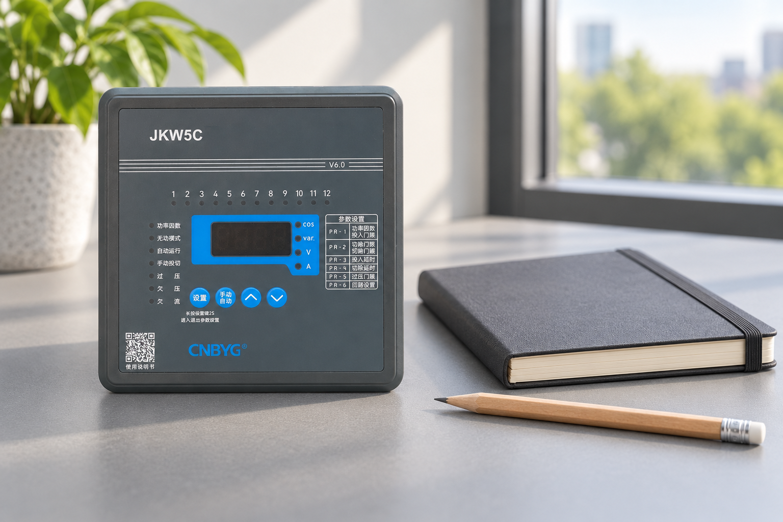
Prevent hunting while evaluating a new sequence
A load that fluctuates close to a switching threshold may cause repeated insertion and removal. Rotation can move those operations between branches without removing the underlying cause. Review compensation step size, measurement stability, deadband, and delay together. Change one relevant parameter at a time so the effects remain understandable.
An oversized smallest stage may overcompensate a lightly loaded installation whichever sequence is selected. Likewise, a measurement point that omits some loads can produce misleading demand. These conditions require engineering correction rather than a different order of outputs. The separate stage hunting troubleshooting guide covers that diagnosis in greater detail.
Keep the distinction between response and stability explicit. A slow sequence may miss a changing load; a fast sequence may exceed switching equipment limits. The suitable compromise depends on the actual installation. Do not copy generic delay values from another panel or shorten discharge waiting time to make a rotation demonstration look smoother.
Document the accepted mode and its limits
The handover record should name the controller model, firmware if available, selected mode, equal-stage groups, excluded outputs, and the procedure used to verify operation. Include the date, approved settings, and who authorized the change. Attach the stage inventory and any supplier explanation of algorithm behavior.
Record what was not tested as well as what passed. For example, observing three normal load cycles does not prove operation under a thermal alarm, reverse power flow, or generator supply. These states need their own reviewed test procedure when relevant. The acceptance record should not imply protection functions that were only discussed.
A maintainable installation lets the next technician understand why a stage was chosen and when it may reconnect. If the terminology in the menu is unclear, retain a verified arrangement and resolve the uncertainty from authoritative equipment documentation. A sequence setting is successful when measured compensation, switching limits, and protection remain correct together.
Further learning: power factor fundamentals
This NPTEL lecture explains the electrical quantities behind compensation demand. It supports the distinction between reactive power and sequence selection; it is not a programming tutorial for a CNBYG controller.
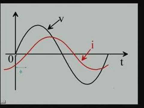
Watch Lecture – 15 Power Factor by NPTEL
Pertanyaan yang sering diajukan
Apakah pengalihan sirkular selalu meningkatkan umur kapasitor?
No. It can distribute operations among compatible stages, but temperature, harmonics, switching transients, component condition, and loading still determine service requirements. Verify operation counts and condition rather than promising a fixed lifetime gain.
Bisakah tahap kapasitor yang tidak sama diputar?
Only if the documented algorithm respects the stage ratings and valid combinations. Do not treat a small trimming stage as interchangeable with a large stage. Check supported ratios and verify actual compensation through controlled observations.
Apakah saklar sirkular sama dengan saklar cepat?
No. Circular describes selection order or duty distribution. Switching speed and reconnection limits belong to the controller timing, discharge arrangement, and switching device specification, and remain applicable in every mode.
Haruskah urutan switching diubah untuk mengatasi pencarian tahap pemulihan?
Investigate the cause first. Rotation can spread repeated operations without eliminating unstable measurements, oversized steps, or inappropriate thresholds. Review those conditions and retain the required discharge and protection limits.