


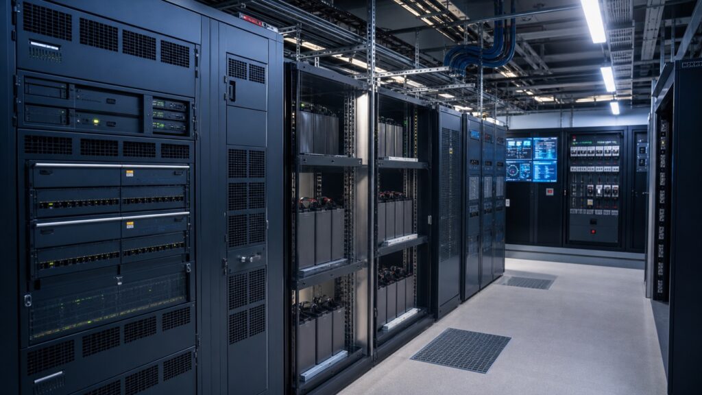
Telecom DC power systems keep radios, transmission equipment, routers, and control electronics operating when the AC utility supply is unstable or unavailable. A typical plant converts incoming AC to a regulated DC bus, supports the load with batteries, distributes protected branch circuits, and reports alarms to a network operations center. For a new site or retrofit, the important decisions are not simply rectifier wattage and battery ampere-hours. Engineers must define the real load profile, autonomy target, redundancy level, allowable voltage window, protection scheme, environmental limits, monitoring interface, and maintenance method. This guide explains that complete selection process without tying it to one proprietary platform.
What a telecom DC power system does
Telecommunications equipment needs continuous power, yet the AC source at a tower, exchange, data room, or roadside cabinet can experience outages, voltage variation, switching events, and generator transfer interruptions. A DC plant separates the critical load from many of those disturbances. Rectifiers supply the operating load and maintain the battery charge during normal service. When AC input disappears, the batteries remain connected to the DC bus and support the load without the transfer delay associated with changing between separate sources.
The familiar “48 V” label describes the nominal system family, not a promise that every point remains at exactly 48.0 V. Battery chemistry, charging state, temperature compensation, cable drop, discharge state, and equipment settings all affect the actual bus voltage. The allowable window must therefore be verified against every connected load and against the battery manufacturer’s instructions. Polarity conventions also require project-specific confirmation; many established telecom installations use a grounded positive conductor and a negative supply bus, but assumptions should never replace drawings and field identification.

Core components and their engineering purpose
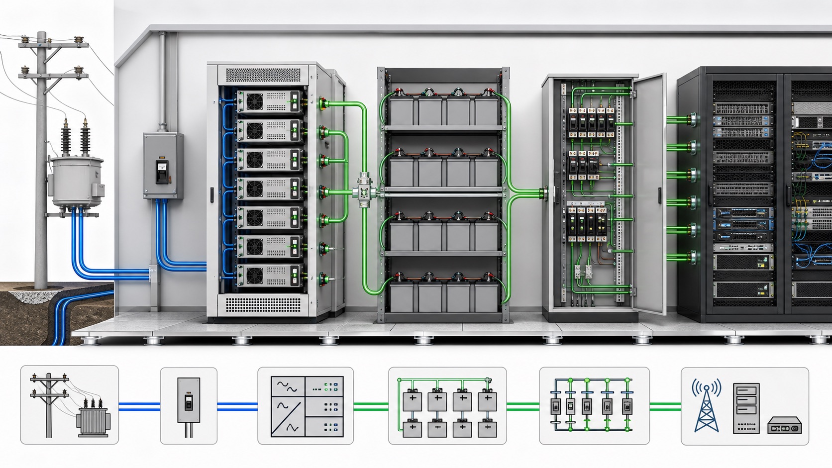
A complete plant is a coordinated system rather than a collection of independent boxes. The AC input section provides isolation, switching, surge protection and branch protection appropriate to the site. Modular rectifiers convert AC to regulated DC and normally share the load. A controller manages charging, current limits, alarms and communications. Battery strings provide stored energy. Low-voltage disconnect functions protect batteries or selected loads from damaging deep discharge. DC distribution panels divide the bus into individually protected feeders. Shunts, transducers and sensors provide the measurements needed for supervision.
| Subsystem | Primary function | Selection evidence to request | Common oversight |
|---|---|---|---|
| AC input and protection | Connects utility or generator power safely to rectifiers | One-line diagram, fault level, protective-device ratings and surge strategy | Checking nominal voltage but not available short-circuit current |
| Rectifier shelf | Feeds the DC load and battery-charging demand | Output curve, efficiency data, derating conditions and module redundancy | Sizing only for today’s average load |
| Battery bank | Maintains service through loss of AC input | Manufacturer discharge data, temperature assumptions and end voltage | Using nameplate ampere-hours as usable capacity |
| DC distribution | Protects and isolates individual load feeders | Feeder schedule, conductor ratings, interruption rating and spare ways | Ignoring voltage drop on long cable runs |
| Controller and monitoring | Coordinates charging, alarms, logging and remote access | Alarm matrix, protocol map, event retention and access-control plan | Buying communications hardware without defining usable alarms |
How to size rectifier capacity
Begin with a load schedule measured or justified by equipment data. Separate continuous load, intermittent load, planned additions, battery recharge demand, and any environmental auxiliaries placed on the DC bus. Convert each item to current at the design bus voltage and account for the worst credible simultaneous operating condition. Do not mix AC input power, DC output power and apparent power in one total.
A practical conceptual check is: required rectifier current equals the maximum service load current plus the permitted battery recharge current, with the desired redundancy applied to the module arrangement. If the load is 180 A and controlled recharge may require 40 A, the operating requirement is 220 A before considering redundancy or environmental derating. In an N+1 design, losing the largest rectifier module must still leave enough available current for the defined duty. The final number must use the selected manufacturer’s output-versus-temperature and input-voltage curves rather than a generic percentage.
Growth allowance should reflect a documented expansion plan. Excessive oversizing can leave modular converters operating inefficiently at light load, while insufficient margin makes a future radio addition an emergency project. A better specification states the initial populated capacity, the ultimate shelf capacity, empty module positions, spare distribution ways, and the trigger for adding the next rectifier.
How to estimate battery autonomy
Battery sizing starts with the required support time and the critical load during an outage. A first-pass energy estimate multiplies DC load power by autonomy hours, but procurement cannot stop there. Real usable capacity depends on discharge rate, end-of-discharge voltage, temperature, aging allowance, parallel-string arrangement, cable losses, and the battery manufacturer’s published discharge tables. Backup duration for a warm indoor exchange may differ materially from the same nominal battery installed in a cold outdoor cabinet.
Define which loads remain energized for the entire outage. Load shedding may disconnect nonessential circuits at a higher voltage threshold while preserving transmission and control functions. Generator start and refueling strategy also influence the autonomy target. The U.S. Department of Energy’s overview of energy storage is useful context, but the detailed design must follow the chosen battery technology, applicable codes and the site owner’s resilience requirements.
For acceptance, record the installed string configuration, commissioning capacity evidence, float settings, temperature compensation settings, terminal torque method, monitoring thresholds and replacement assumptions. These records make later capacity tests meaningful. A battery alarm without a traceable baseline tells the operator that something changed, but not whether the remaining autonomy meets the service objective.
Distribution, protection and voltage drop
Every outgoing feeder needs a defined load, conductor, route, protective device and isolation method. Protection must coordinate with conductor capacity and the prospective fault current of the battery-supported bus. Batteries can deliver high fault current even when the AC source is absent, so technicians must treat the DC plant as energized until an approved isolation and verification process proves otherwise.
Voltage drop is often the limiting issue on long tower or campus runs. Calculate the round-trip conductor resistance at the applicable temperature and multiply it by the design current. Check both normal operation and the low-bus condition near the end of battery discharge. A load that operates correctly at the distribution panel can still reset if the voltage at its terminals falls outside its input range. Record the permissible drop for each feeder instead of using one informal rule for all circuits.
DC protection has different interruption behavior from AC protection because current does not pass through a natural zero crossing each cycle. Use devices explicitly rated for the system’s DC voltage, polarity arrangement and fault duty. Field substitutions based only on matching ampere ratings are unsafe. The Sumber daya keselamatan kelistrikan OSHA provide general workplace guidance; qualified personnel must also apply local codes, approved procedures and equipment instructions.
Power quality at the AC input still matters
A DC plant protects the telecom load from a direct interruption, but its rectifiers remain nonlinear loads on the upstream AC system. Large sites should evaluate phase loading, input current harmonics, power factor, generator compatibility and voltage distortion at the point of connection. Problems may appear only when many rectifier modules operate together or when a generator supplies the site.
A multifunction power instrument can provide continuous upstream measurements, while temporary studies can capture waveform and harmonic detail. The distinction between real power, reactive power and power factor is explained in our guide to daya aktif dan reaktif. If rectifier harmonics are affecting the shared AC bus, review the measurement approach before selecting an active harmonic filter. Mitigation should follow verified site data rather than a percentage copied from another facility.
Monitoring, alarms and cybersecurity
Useful monitoring begins with an alarm response plan. At minimum, operators normally need AC input failure, rectifier module failure, high and low DC voltage, battery disconnect state, distribution fuse or breaker alarms, battery temperature, controller communication loss and environmental alarms relevant to the enclosure. Each alarm should have severity, delay, destination, timestamp behavior and a documented operator action.
Trend data is just as important as instantaneous alarms. Gradual increases in load current, repeated high-temperature periods, widening string imbalance or frequent generator transfers can reveal deterioration before service is lost. Store measurements at an interval that supports diagnosis, and confirm how long records remain available after a controller reboot or network outage.
Remote access must be managed as an operational technology interface, not treated as a convenience feature. Define accounts, authentication, network segmentation, firmware ownership, backup and recovery, and the process for disabling unused services. The Kerangka Kerja Keamanan Siber NIST offers a general structure for identifying, protecting, detecting, responding to and recovering from cyber risks; the site owner should translate that structure into system-specific controls.

Commissioning and maintenance checklist
Commissioning should prove the complete operating sequence. Verify drawings and labels; inspect conductor routing, polarity and torque records; confirm protective-device ratings; check controller configuration; test remote alarms; demonstrate rectifier load sharing; simulate loss and restoration of AC input under an approved method; verify battery and load-disconnect logic; and record baseline voltage, current and temperature values. Where generator support exists, test the actual transfer and loading sequence rather than assuming independent equipment tests prove system performance.
Maintenance intervals should follow the battery, rectifier and site owner requirements. A useful visit reviews event logs, fan and filter condition, ventilation, corrosion, abnormal odor, loose or overheated connections, battery appearance, string voltage balance, sensor operation, alarm transmission and spare-module condition. Thermographic inspection can support condition assessment when performed by qualified personnel under an approved energized-work process, but it does not replace torque records or electrical testing.
Keep firmware files, configuration backups, alarm maps, one-line diagrams, feeder schedules and spare-parts records under change control. After any expansion, repeat the capacity and redundancy checks. A plant can look healthy while running but fail its resilience objective because the added load consumed the reserved rectifier module or reduced battery autonomy below the agreed threshold.
Procurement questions for suppliers
- What input range, frequency range and environmental derating apply to the quoted rectifier output?
- How is N+1 or other redundancy demonstrated at the project’s maximum service and recharge load?
- Which battery technologies and charging profiles are supported, and who owns final settings?
- What are the rated DC interruption capabilities of distribution devices at the specified fault level?
- Which protocols, alarm points, timestamps and historical data can the controller export?
- What commissioning tests, records, training, spares and warranty boundaries are included?
- How will future load additions be accommodated without changing the cabinet or bus architecture?
For projects requiring custom metering, panel integration or supplier coordination, CNBYG’s Layanan OEM dan ODM can support specification discussions. Provide the one-line diagram, load schedule, AC source details, DC voltage window, autonomy target, environment, communications needs and applicable standards so the engineering review begins with evidence.
Video: a refresher on electric power
The following Khan Academy lesson reviews the relationship among voltage, current and power. It is background material only; it does not replace telecom plant design calculations or manufacturer instructions.

Watch the electric power lesson on YouTube.
Pertanyaan yang sering diajukan
Mengapa situs telekomunikasi umumnya menggunakan daya DC?
Baterai dapat tetap terhubung ke bus DC, memungkinkan beban kritis untuk terus beroperasi saat input AC mengalami kegagalan tanpa menunggu transfer terpisah. Tegangan nominal yang pasti, susunan pembumian, dan jendela operasional yang diizinkan tetap spesifik untuk setiap proyek.
Berapa banyak modul penyearah (rectifier) yang dibutuhkan oleh sistem catu daya DC telekomunikasi?
Tentukan beban simultan maksimum, arus pengisian baterai yang diizinkan, penurunan daya lingkungan (derating), dan tujuan redundansi. Dalam susunan N+1, modul yang tersisa harus menanggung beban yang ditentukan setelah modul terbesar tidak tersedia.
Dapatkah ampere-jam baterai dibagi dengan arus beban untuk menjamin waktu proses?
Tidak. Pembagian tersebut hanyalah perkiraan awal. Otonomi akhir harus menggunakan data pelepasan pabrikan dan memperhitungkan tingkat pelepasan, tegangan akhir, suhu, penuaan, pengkabelan, dan urutan pemutusan beban yang sebenarnya.
Apakah pembangkit DC menghilangkan masalah kualitas daya hulu?
No. Rectifiers isolate the critical load from some disturbances, but they still interact with the AC source. Phase loading, harmonic current, voltage distortion, generator compatibility and grounding should be assessed at the actual site.
What records should be retained after commissioning?
Keep approved drawings, feeder schedules, protection settings, controller configuration, alarm test results, battery baseline data, torque records, firmware versions, capacity evidence and the final commissioning report.