

A textile mill can have hundreds of drives spread across spinning, winding, weaving, dyeing and finishing. A single average reading can hide the machine group that actually changes the feeder spectrum. The practical starting point is a state-tagged feeder review: match current spectra and voltage records to the same production state, then compare the result with the PCC.


Split the mill into production drive groups
Start with the machine groups that share a feeder or transformer: spinning frames, winding, weaving, dyeing, finishing and material handling. The group names matter less than a repeatable state tag. Record which drives are running, their speed or load command, and whether a line is starting, steady, changing recipe or stopped.
A VFD is a non-linear load at its input. Nidec’s technical note defines the PCC and TDD concepts and explains that rectifier charging creates the line-side distortion. That is useful vocabulary, but it is not a textile-mill result.
Compare feeder and PCC records
Use the same time base for the machine feeder and upstream PCC. Capture phase current, voltage, spectrum, demand current, power factor and event markers. A feeder can show a high current distortion while the PCC sees a different result after other loads combine; the reverse can also happen when several feeders contribute.
| Review layer | State tag | Pertanyaan keputusan |
|---|---|---|
| Machine group | start, run, stop, recipe change | Which group changes the spectrum? |
| Feeder | group combination and speed | Is the distortion local or shared? |
| Transformer / bus | shift and production window | Do other loads amplify or cancel it? |
| PCC | same timestamp and demand window | What should the upstream design address? |
Separate line-side harmonics from motor-side symptoms
Dyeing or winding equipment may also produce cable, bearing or common-mode complaints. Those are not automatically a PCC harmonic problem. Keep motor-terminal waveform, cable length and shaft-current evidence in a separate work item while the feeder study answers the line-side question.

Build a repeatable feeder review
- Freeze the one-line and CT locations before the test.
- Name the machine states in the operator or PLC log.
- Run a complete production cycle, including a start and a recipe change.
- Compare spectra at the feeder and PCC with the same time window.
- Only then compare a reactor, DC choke, passive filter, AFE or APF path.
The choice is conditional. Source impedance, drive topology, grouping, available space and the required boundary all matter. A filter that is reasonable for a single machine may be wrong for a mixed feeder.
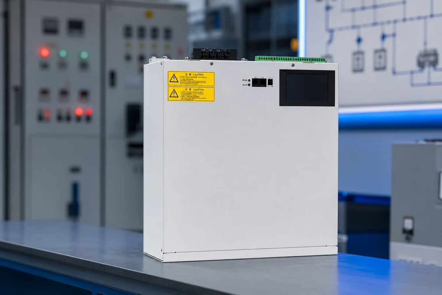
When an AHF becomes a textile-feeder option
CNBYG’s AHF/APF product path can be the next step after a textile feeder record establishes a line-side harmonic need. Request the model datasheet, CT scheme, current headroom, thermal and enclosure limits, and commissioning procedure. Do not infer textile application fit, certification or performance from a generic AHF page.
Gunakan Power Quality System pillar, then continue to industrial VFD selection guidance and the CT placement article when the boundary is ready for engineering review.