Seleção de Contactor de Serviço de Condensador para Painéis APFC
Capacitor duty contactor selection must account for capacitor-switching inrush, steady-state current, available fault level, step kvar, voltage, frequency, ambient temperature, switching rate, discharge time, upstream capacitance, and coordination with protection. A standard motor contactor with the same ampere rating is not automatically suitable. Capacitor-duty designs commonly use early-make auxiliary contacts and pre-insertion resistors or another manufacturer-defined method to limit the first transient before the main contacts close. Select from tested manufacturer tables for the complete duty, then verify coil voltage, utilization category, enclosure conditions, conductor size, protection, and control timing. Do not size from panel photographs or nominal current alone.
- Why capacitor switching is different
- Understand the pre-insertion path
- Establish the electrical duty
- Check control and mechanical details
- Coordinate discharge and reconnection
- Protection and reactor coordination
- Failure symptoms and evidence
- What to put in the purchase specification
- Factory and site acceptance evidence
- Review the contactor after an initial service period
- Tabela de decisão
- Fontes e aprendizagem adicional
- Perguntas frequentes
Why capacitor switching is different
An uncharged capacitor initially presents a very low impedance to a sudden voltage difference. Closing onto the bus can therefore create a high, short-duration current limited by source impedance, conductors, reactors, resistors, and any already energized capacitors. Back-to-back switching can be more severe because an energized bank contributes to the transient. The contactor must withstand repeated making duty without contact welding, excessive erosion, nuisance operation, or damage to nearby components. The event is transient, so a clamp meter's normal current display cannot characterize it.
Understand the pre-insertion path
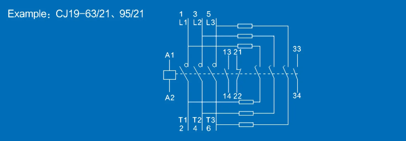
Many capacitor-duty contactors close auxiliary contacts through damping resistors before the main contacts. The temporary path limits the transient; the main contacts then carry steady current and the auxiliary path is removed from continuous duty. Exact timing and construction belong to the tested device design. Do not modify resistor values, auxiliary blocks, or mechanical linkages. Inspect replacement parts as a complete assembly. A contactor that appears physically compatible may not reproduce the intended sequence or withstand the same duty.
Establish the electrical duty
Record line voltage, frequency, capacitor step kvar at actual voltage, connection, reactor presence, prospective short-circuit current, upstream transformer, other energized banks, and expected switching frequency. Calculate balanced line current from kvar and voltage as an initial check, but use the manufacturer's capacitor-duty selection table for final device choice. Capacitor current can exceed the ideal nameplate calculation because of voltage variation, capacitance tolerance, and harmonic content. Determine whether the application is single-stage, multi-stage, or back-to-back switching and state the worst operating condition.
Check control and mechanical details
Match the coil voltage, frequency or DC specification, control-power tolerance, and controller output. Confirm auxiliary contacts needed for feedback, interlocks, and alarms. Check mounting orientation, terminal capacity, tightening torque, mechanical clearances, and replacement accessibility. The enclosure temperature can be higher than room temperature; apply the declared derating and ventilation rules. A larger frame is not a cure for incorrect coil voltage, excessive switching frequency, or poor thermal design.
Tabela de decisão
| Entrada de seleção | Why it changes the duty | Evidência | Erro comum |
|---|---|---|---|
| Step kvar, voltage and frequency | Sets fundamental branch current | Approved bank schedule | Selecting by frame size alone |
| Already energized stages | Can create back-to-back transient contribution | Single-line and switching sequence | Assuming only source inrush matters |
| Reactor or damping method | Changes impedance and transient behavior | Approved reactor-capacitor assembly | Mixing unmatched components |
| Switching rate and minimum off-time | Affects thermal stress, wear and residual voltage | Load profile and controller settings | Using very short delays |
| Coil and enclosure conditions | Affects reliable closing and temperature rise | Control schematic and thermal design | Upsizing contacts while ignoring coil voltage |
| Protection and fault level | Defines coordination and withstand needs | Short-circuit and protection study | cURL Too many subrequests by single Worker invocation. To configure this limit, refer to https://developers.cloudflare.com/workers/wrangler/configuration/#limits |
Coordinate discharge and reconnection
cURL Too many subrequests by single Worker invocation. To configure this limit, refer to https://developers.cloudflare.com/workers/wrangler/configuration/#limits.
Protection and reactor coordination
cURL Too many subrequests by single Worker invocation. To configure this limit, refer to https://developers.cloudflare.com/workers/wrangler/configuration/#limits.
Failure symptoms and evidence
cURL Too many subrequests by single Worker invocation. To configure this limit, refer to https://developers.cloudflare.com/workers/wrangler/configuration/#limits.
What to put in the purchase specification
cURL Too many subrequests by single Worker invocation. To configure this limit, refer to https://developers.cloudflare.com/workers/wrangler/configuration/#limits.
Factory and site acceptance evidence
cURL Too many subrequests by single Worker invocation. To configure this limit, refer to https://developers.cloudflare.com/workers/wrangler/configuration/#limits.
Review the contactor after an initial service period
cURL Too many subrequests by single Worker invocation. To configure this limit, refer to https://developers.cloudflare.com/workers/wrangler/configuration/#limits.
Como este tema se relaciona com os equipamentos da CNBYG
Este guia suporta discussões sobre especificação e comissionamento para o cURL Too many subrequests by single Worker invocation. To configure this limit, refer to https://developers.cloudflare.com/workers/wrangler/configuration/#limits linha de produtos. Os dados do produto devem ser verificados em relação à tensão do sistema real, ao perfil de carga, às medições de harmônicos, ao projeto de proteção, às condições ambientais e aos requisitos aplicáveis do projeto. Partilhe um diagrama de linha única e medições representativas antes de solicitar uma recomendação de modelo.
Guia técnico da CNBYG
- compare a power contactor and capacitor-duty contactor
- understand point-on-wave capacitor switching
- review contactor duty in harmonic networks
Fontes e aprendizagem adicional
O Guia de sistemas de motorização do Departamento de Energia dos EUA explica onde a correção do fator de potência fixa e automaticamente comutada pode se adequar aos padrões de carga industrial. OSHA 1910.333 fornece a base de referência dos EUA para as práticas de desenergização e trabalhos elétricos. IEEE 519 é a referência do órgão de normas para o controle harmônico no ponto de acoplamento comum. Aplique as edições atuais e os requisitos locais para o projeto.
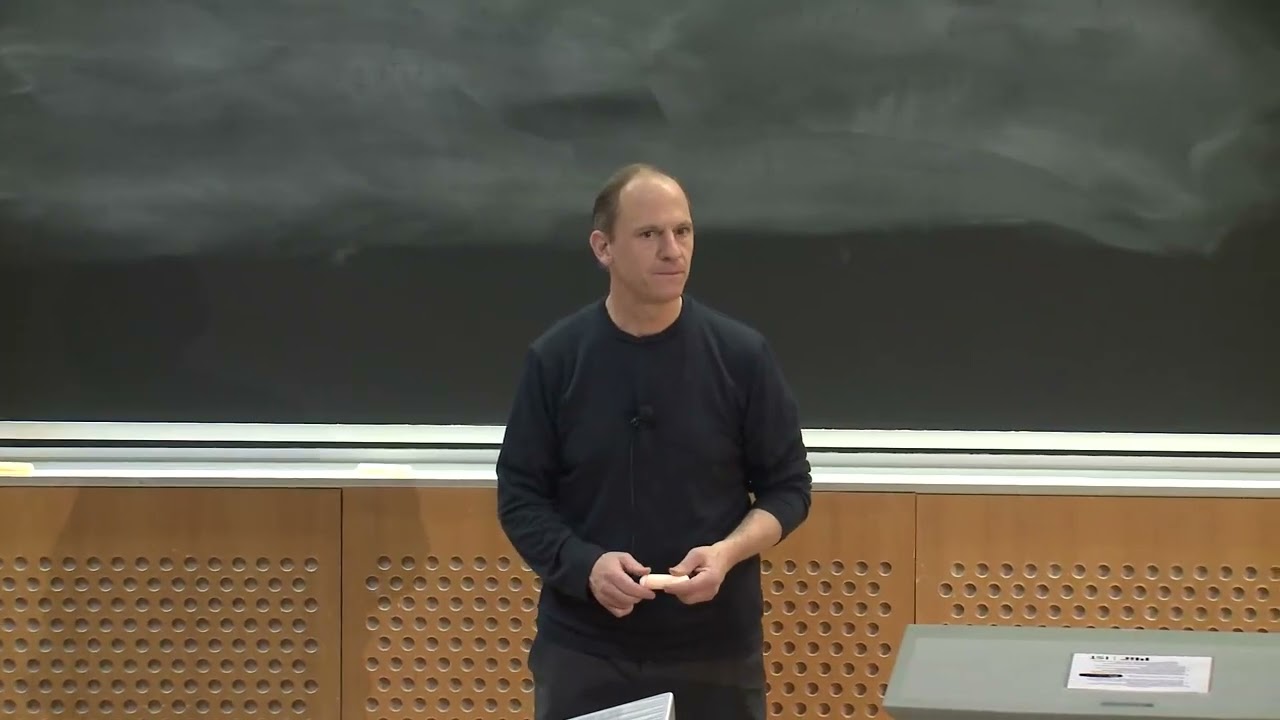
Aprimoramento: MIT OpenCourseWare – Aula 4: Fator de Potência. A palestra do MIT explica o fator de potência e a distorção; não substitui as instruções específicas para o equipamento do projeto.
Perguntas frequentes
Can a normal contactor switch a capacitor bank?
Utilize apenas um dispositivo e classificação explicitamente aprovados para a função de comutação de condensadores. Uma classificação de corrente do motor igual não é prova suficiente.
Por que é que os contactores de condensadores usam resistências?
Em projetos com resistências de pré-inserção, elas limitam temporariamente o transiente de fecho antes que os contactos principais suportem corrente constante.
How is capacitor contactor current calculated?
Para um ramo trifásico equilibrado, a corrente ideal é Q dividida por √3 vezes pela tensão de linha, mas a seleção final necessita de tabelas de duty do fabricante e fatores de aplicação.
Why is minimum off-time important?
It allows the capacitor to discharge before reconnection, reducing the voltage difference and transient stress.
Nota final de engenharia: Trate as fórmulas e listas de verificação como ferramentas de verificação. A instalação, proteção, comissionamento e testes energizados devem ser realizados por pessoal qualificado, utilizando desenhos aprovados, manuais do produto, estudos e procedimentos de segurança no local.