Como Conectar um Controlador APFC a um Banco de Capacitores
APFC controller wiring must match the controller’s documented voltage input, CT input, control supply and output interface to the capacitor bank’s actual circuit. There is no safe universal terminal diagram for every controller. Start with the approved panel drawing and exact model manual, map each signal by function, and verify the measurement relationship before automatic switching is enabled.
This guide explains the engineering checks behind a correct installation. It deliberately avoids terminal numbers, improvised live tests and generic wire-size prescriptions. Installation and commissioning belong to qualified personnel following the site’s electrical safety procedure and the applicable equipment documentation.
Understand the four wiring functions
The controller needs a supply to operate, a voltage reference, a current measurement and a way to command capacitor stages. These functions may share connections in some designs and remain separate in others. An apparently identical controller front panel does not establish that rear terminals or supply requirements are the same.
The current measurement usually comes from a CT at a defined electrical boundary. The voltage reference must be associated with the current input in the relationship expected by the controller. The outputs may operate contactor coils, interposing relays or a compatible switching module. Each interface needs its own rating and connection check.
O CNBYG JKW reactive-power controller is a relevant product for this application. Obtain its exact model instructions and compare them with the panel drawing. A product illustration cannot establish whether a particular output is a dry contact, powered signal or another interface.
Assemble the documents before connecting anything
Collect the single-line diagram, control schematic, terminal schedule, CT data, capacitor stage schedule and protective-device information. Confirm the drawing revision matches the cabinet. If modifications have occurred, mark them and obtain an approved corrected drawing instead of relying on an undocumented technician’s recollection.
Record the system voltage, frequency, conductor arrangement and intended compensation boundary. Identify separate control supplies, generator operation and transfer equipment. A controller that is appropriate for one normal supply mode may need additional permissives or different sensing arrangements when the plant transfers to another source.
Check the controller’s mounting and environmental requirements as well. Wiring accuracy cannot compensate for a supply rating mismatch, unsuitable enclosure environment or incorrect installation clearance. Verify these constraints before a commissioning team reaches the stage where it is expected to energize the panel.
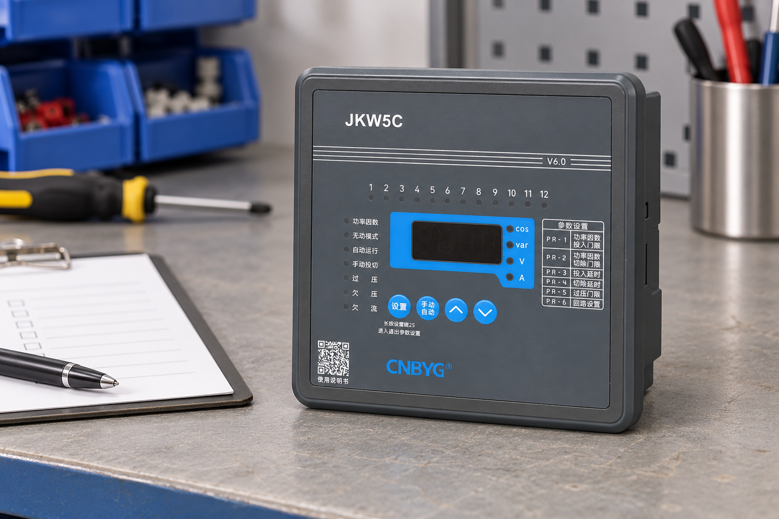
Reference-based illustration. Use the approved manufacturer’s drawing for actual connections.
Map each circuit by function
| Circuito | Requisitos que devem corresponder | Prova para registrar |
|---|---|---|
| Controller supply | Required type, rating and protective arrangement | Model manual and control schematic |
| Referência de tensão | Correct electrical boundary and phase association | Drawing and qualified verification record |
| CT input | Ratio, secondary rating, polarity and measurement direction | CT label, installation details and controller settings |
| Stage outputs | Output type and switching-device input requirements | Interface specification and stage schedule |
| Common or enable circuit | Required operating permissives and separation | Interlock diagram and test procedure |
| Feedback or alarms | Meaning of each signal and fail behavior | Cause-and-effect schedule |
This is a functional checklist, not a connection diagram. The correct terminal assignment, conductor selection, segregation and protective arrangement are established from the actual product documentation and applicable installation rules.
Place the CT at the intended compensation boundary
The CT must measure the load and compensation relationship the controller is intended to regulate. A misplaced CT can make the controller respond to only part of the plant or fail to observe the capacitor bank’s effect. First define whether the objective is regulation at the main incomer, one distribution board or a dedicated load.
Trace the capacitor bank connection relative to the CT location on the single-line diagram. Do not choose a location simply because it is convenient inside the cabinet. Where several sources or bus sections exist, identify which current paths are measured in every operating mode. A design that works on the utility source can behave differently after a transfer.
Análise Configuração da razão APFC CT before programming the controller. Ratio scaling, input rating and physical CT location are separate checks. Setting the correct ratio will not fix a CT placed on the wrong feeder or a voltage reference associated with the wrong phase.
Respect CT-secondary safety
A current transformer’s secondary circuit requires specific safe handling. Do not disconnect it casually while primary current may flow, and do not treat it as a normal low-energy control wire. Qualified personnel should use the approved isolation and shorting arrangements for the installed CT system.
Before modifications, identify whether test blocks, shorting terminals and earthing arrangements are present and suitable. Follow the CT manufacturer’s instructions and site procedure. This article does not provide a live CT disconnection sequence because that sequence depends on the actual installation and its protective provisions.
For electrical work generally, consult the OSHA requirements for selection and use of work practices, together with local regulations. The separate cURL Too many subrequests by single Worker invocation. To configure this limit, refer to https://developers.cloudflare.com/workers/wrangler/configuration/#limits cURL Too many subrequests by single Worker invocation. To configure this limit, refer to https://developers.cloudflare.com/workers/wrangler/configuration/#limits.
cURL Too many subrequests by single Worker invocation. To configure this limit, refer to https://developers.cloudflare.com/workers/wrangler/configuration/#limits
cURL Too many subrequests by single Worker invocation. To configure this limit, refer to https://developers.cloudflare.com/workers/wrangler/configuration/#limits.
cURL Too many subrequests by single Worker invocation. To configure this limit, refer to https://developers.cloudflare.com/workers/wrangler/configuration/#limits.
cURL Too many subrequests by single Worker invocation. To configure this limit, refer to https://developers.cloudflare.com/workers/wrangler/configuration/#limits cURL Too many subrequests by single Worker invocation. To configure this limit, refer to https://developers.cloudflare.com/workers/wrangler/configuration/#limits cURL Too many subrequests by single Worker invocation. To configure this limit, refer to https://developers.cloudflare.com/workers/wrangler/configuration/#limits.
cURL Too many subrequests by single Worker invocation. To configure this limit, refer to https://developers.cloudflare.com/workers/wrangler/configuration/#limits
Confirm that each output can operate the intended interface within its rating. If an interposing relay is specified, preserve its function and check its coil supply, contact duty and protective provisions. Do not assume the controller should directly carry a contactor coil simply because the wiring can physically be connected.
Number the outputs and associate each with a documented capacitor stage. Record the stage kvar, reactor if fitted, switching technology and control interface. An output-to-stage mismatch can confuse commissioning and cause the controller to add a different amount of reactive power from the amount programmed.
Review shared common connections carefully. A mistaken common or cross-connected supply can affect several stages and introduce an unexpected energy source during maintenance. The final schematic should make the origin of each supply and the isolation boundary understandable without opening the panel.
Preserve interlocks and protection
Automatic demand does not override a protective condition. The panel should permit a stage only when its documented safety and operating conditions are satisfied. These may include valid measurement, supply availability, thermal limits and capacitor discharge eligibility. The exact requirements are established by the design.
Do not bypass an interlock merely to demonstrate that an output can energize. Test it through the approved procedure and record both the blocked and permitted states. Where a protection signal fails, determine the intended fail behavior before returning the bank to automatic operation.
A manually selected mode also needs review. Some panels preserve all protective blocking in manual mode, while other arrangements require procedural controls. Confirm the actual design; a button labeled manual is not permission to ignore capacitor state or source conditions.
Use a staged commissioning plan
Begin with isolated inspection and documentation checks. Verify conductor identification, terminal security, segregation, protective devices and drawing accuracy using the specified methods. Keep the bank inhibited until the measurement inputs and controller configuration have been accepted.
Then verify the measurement response under controlled conditions. Confirm the load direction and phase relationship before allowing stages to operate. When the approved procedure permits stage testing, check one documented stage at a time and compare the observed reactive-power change with its expected role. Record any uncertainty before advancing to automatic control.
O capacitor bank sizing guide gives useful system context. Stage sizing and wiring are connected: a correctly wired controller can still perform poorly if the programmed stage capacities do not describe the real bank.
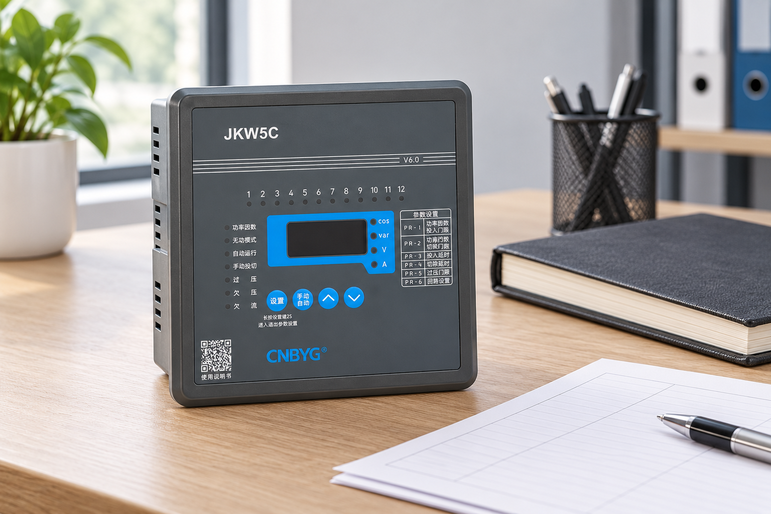
Reference-based illustration. Commissioning values must be measured at the real panel.
Handover and future modifications
Provide the final drawing, settings record, CT identification, stage mapping and commissioning results. Include alarm meanings and the authorized isolation procedure. Keep a controlled copy where maintenance teams can find it; an accurate document is part of the installation, not an optional administrative extra.
Whenever a stage, CT or supply arrangement changes, review the mapping and configuration together. Do not leave the old drawing in service after a temporary modification becomes permanent. Future fault diagnosis depends on knowing what is actually connected and what each indication means.
Aprimoramento de conhecimentos
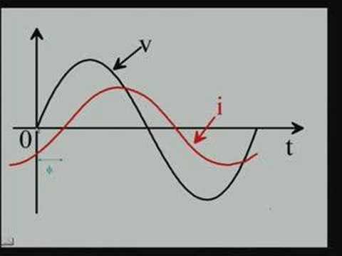
Watch Lecture – 15 Power Factor
Perguntas frequentes
Can I use a generic APFC wiring diagram?
Use-o apenas para compreender funções. Os números dos terminais, classificações e relações de fase devem vir do manual exato do controlador e do desenho aprovado do painel.
Porque é que o controlador consegue apresentar o fator de potência, mas comuta incorretamente?
Uma exibição plausível não prova a localização correta do CT, polaridade, relação ou associação de tensão. Verifique toda a relação de medição antes de alterar as configurações de comutação.
Can a controller output drive any capacitor switch?
Não. Combine o tipo de saída, a classificação e o arranjo de alimentação com a entrada do dispositivo de comutação. Use a interface de interposição especificada quando o projeto exigir uma.
What must be saved after commissioning?
Final drawings, CT data, output-to-stage mapping, settings, protection checks and measured acceptance results. These records support safe maintenance and reliable later changes.