


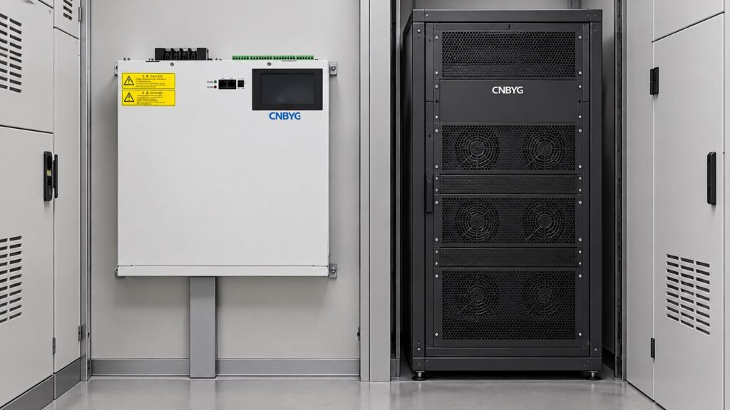
ASVG vs AHF: Functions and Selection
ASVG and AHF equipment can both use power electronics and current control, but they are not interchangeable labels. An advanced static var generator (ASVG) is normally selected first for reactive power, power-factor and voltage-support duties, while an active harmonic filter (AHF) is selected for harmonic-current mitigation. Some platforms combine reactive and harmonic functions, yet the current budget, measurement boundary, control priority and installation limits still determine what the system can deliver.
O CNBYG SVG and ASVG product page and the CNBYG AHF product page should be used with the model datasheets. The correct choice is based on measured current and voltage conditions, not on the word “active” in a product name.
Start with the electrical problem
Write the problem in measurable terms. Is the source penalized for poor displacement power factor? Are capacitors switching frequently? Is neutral current high? Are VFDs, rectifiers or UPS units creating unacceptable harmonic current? Does a generator transfer change the voltage or short-circuit strength? One installation may have several problems, but each needs a defined target and measurement point.
An ASVG typically generates or absorbs reactive current. An AHF synthesizes a current that opposes selected harmonic components. A combined unit can share a converter between those objectives, but “combined” does not mean unlimited simultaneous capacity. The selection must state which function has priority when the current limit is reached.

Functional comparison
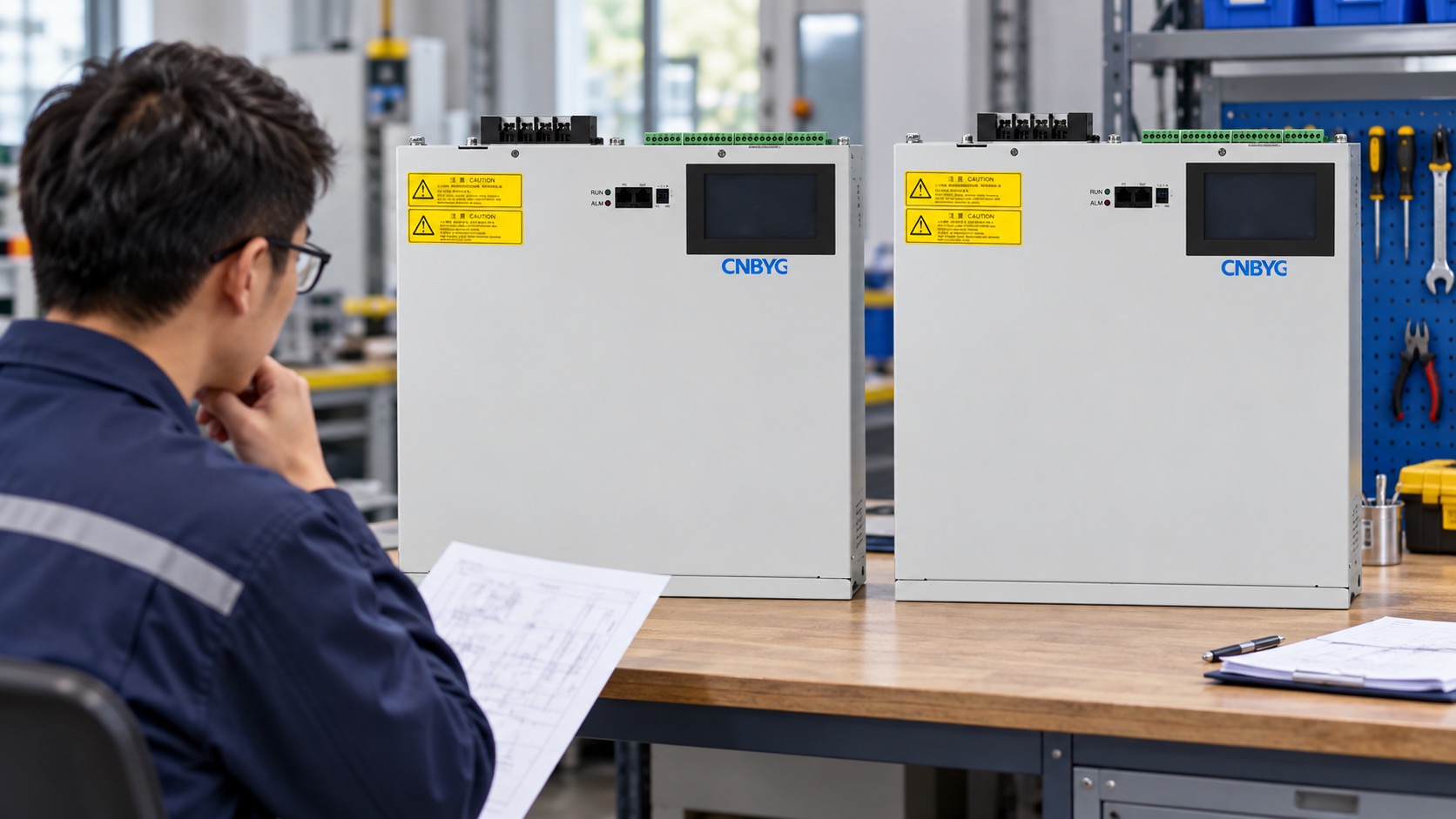
Use this table to frame an RFQ and a site study. Confirm every row against the selected model.
| Pergunta | ASVG emphasis | AHF emphasis |
|---|---|---|
| Primary objective | Reactive current, power factor and voltage support. | Harmonic current reduction and waveform quality. |
| Main measurement | kW, kvar, PF, voltage and current direction. | THD, individual harmonic orders, RMS current and phase. |
| Typical load issue | Motors, transformers, fluctuating kvar or leading conditions. | VFDs, rectifiers, UPS systems and nonlinear loads. |
| Current allocation | Reactive and possibly unbalance functions share the converter. | Selected harmonic orders and possible reactive functions share the converter. |
| Selection boundary | Bus or incomer where reactive performance is required. | Point where harmonic current is measured and limits apply. |
| Acceptance evidence | PF, kvar, voltage, current and response under load states. | THD, harmonic spectrum, RMS current and response under load states. |
| Common risk | CT polarity, undersizing or overcompensation. | Wrong harmonic target, insufficient current or changed load spectrum. |
Measurement and CT boundary
Both technologies depend on correct measurement. Confirm CT ratio, polarity, phase assignment, location, burden and controller input range. Compare the equipment display with an independent analyzer at the same time and electrical point. A reversed CT can make an ASVG chase the wrong reactive direction; an incorrect phase reference can make an AHF inject the wrong harmonic compensation.
O SVG reactive-current guide explains why a display value cannot be interpreted without a defined boundary. For AHF work, preserve individual harmonic orders rather than relying only on a single THD number. A lower total THD can hide a new resonance or a worse fifth harmonic if the spectrum is not saved.
Capacity and priority
Convert each requirement into current at the actual voltage. Reactive kvar, harmonic RMS current and unbalance current are not always additive in a simple nameplate calculation. Some components are orthogonal, some overlap, and all are limited by the converter’s voltage, switching, thermal and protection boundaries.
Ask the supplier for separate capability information: reactive current at minimum voltage, harmonic current by order, maximum simultaneous duty, ambient derating, overload duration and the behavior when the current limit is reached. Define whether reactive power or harmonic filtering has priority. If a plant controller can change the priority, record who owns that command and what happens if communication is lost.
Installation differences
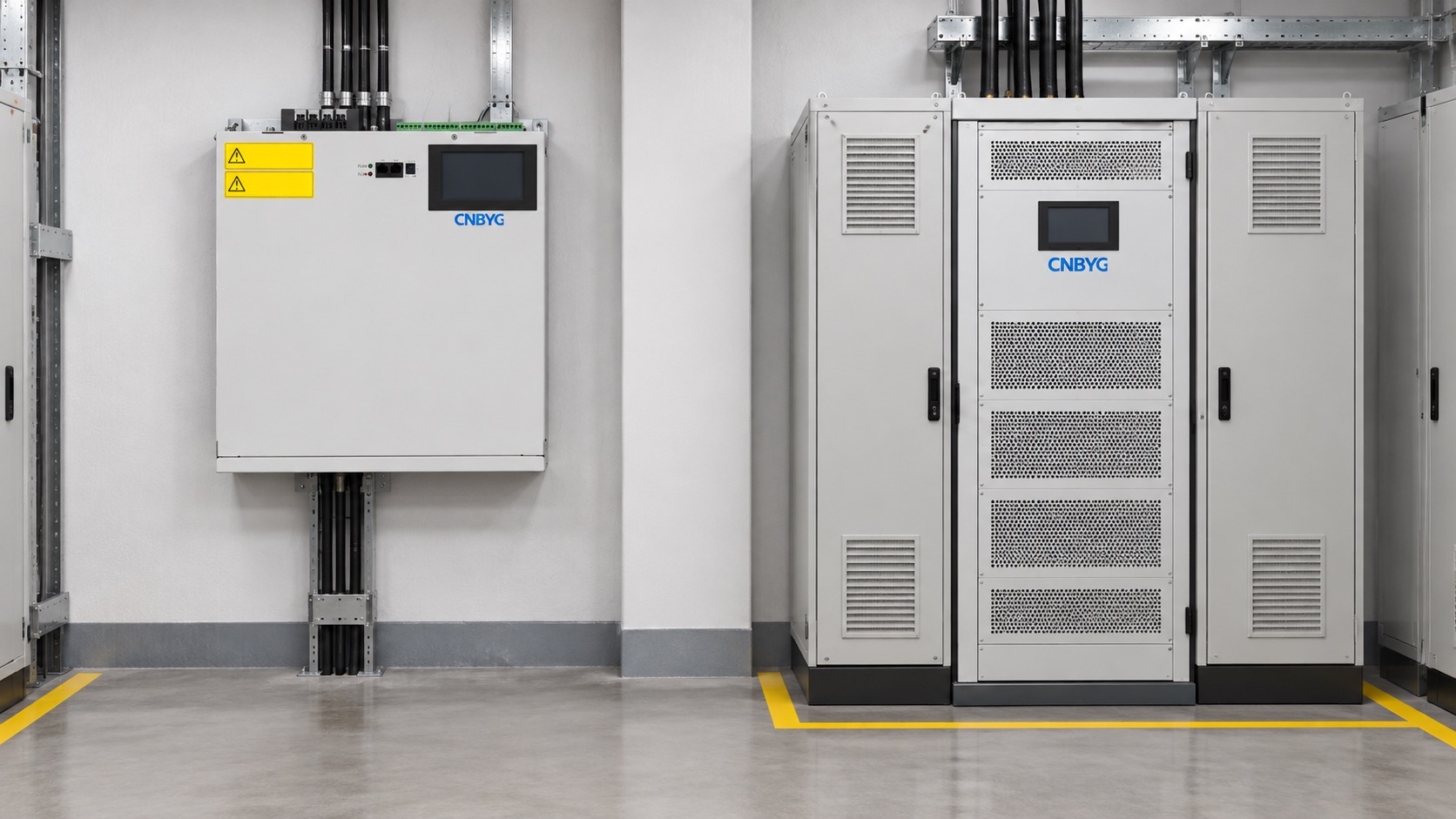
An ASVG wall unit and an AHF rack module can have different mounting, cable-entry, cooling, bypass and service requirements. Review cabinet depth, rails, ventilation, heat rejection, clearances, breaker coordination and isolation points. A product that fits an empty space may still fail the thermal or short-circuit review.
O wall-mounted versus rack-mounted SVG guide provides a practical installation comparison. For a mixed ASVG/AHF cabinet, also verify that airflow from one module does not heat the inlet of another and that the bus and CT arrangement preserves the intended measurement boundary.
When a combined platform is useful
A combined ASVG/AHF platform can reduce footprint and simplify a project when the same load group needs fast reactive and harmonic support, the controller can prioritize the objectives, and the supplier provides a clear capability curve. It can be attractive where cabinet space, common communications and one coordinated service plan matter.
It may be better to use separate units when the reactive and harmonic duties occur at different buses, when one function must remain available during service of the other, or when the required current is large enough that independent capacity and redundancy are more valuable than a common enclosure. Separate units can also make the acceptance criteria easier to isolate.
Selection workflow
- Capture voltage, kW, kvar, PF, phase current, THD and harmonic spectrum at the intended boundary.
- Mark the load states that create the highest reactive and harmonic duties.
- Define the required objective and the consequence of a current limit.
- Compare ASVG, AHF and combined capability curves at the measured voltage and ambient.
- Check CTs, protection, bus, cable, cooling, mounting, communication and service access.
- Write acceptance cases for reactive performance, harmonic performance and combined priority behavior.
- Keep the original traces, settings and limitations in the handover pack.
Commissioning and acceptance
Test the measurement chain before enabling compensation. Verify phase sequence, CT polarity, voltage reference and sign convention. Start with one objective at a conservative target, then add the second objective after confirming the current allocation. Use synchronized traces so the reviewer can see the load, voltage, output and result together.
For general power-quality measurement practice, IEC 61000-4-30 defines measurement methods and aggregation concepts; the IEC catalogue entry is the authoritative scope reference. The standard does not replace model-specific protection or commissioning instructions.
Engineering distinctions that change the answer
Reactive current is linked to the fundamental component and the phase relationship between voltage and current. Harmonic current is a waveform problem: the fifth, seventh, eleventh and other components can circulate even when the displacement power factor looks acceptable. A plant can therefore need both functions, but the measurements must not be collapsed into one number. Save the fundamental kvar and the harmonic spectrum separately.
The source impedance also matters. An AHF can reduce current distortion at its measurement point without guaranteeing the same voltage distortion at every downstream bus. An ASVG can support voltage or reactive current without removing the harmonic source. Check where the utility or process limit is defined and whether the proposed equipment is connected close enough to that boundary.
Consider the operating envelope. A large motor start may create a short reactive demand but little harmonic current; a VFD production run may do the opposite. A generator transfer can change both. Use time-correlated traces to identify coincident peaks before selecting a combined platform. If the peaks do not coincide, separate units may deliver more usable capacity because each converter can be sized for its own duty.
Service and redundancy are part of selection. Ask whether the plant can tolerate a common controller, shared DC link or common cooling path being unavailable. Define safe bypass and isolation for each function. Record fan, filter, control-board and firmware dependencies, and state whether a replacement must match a hardware revision. These details often decide between a compact combined installation and two independent units.
Finally, require a clear limitation statement. The supplier should state the voltage, ambient, load, harmonic spectrum and priority assumptions behind the quoted result. A transparent limitation is more useful than a larger nominal number that cannot be verified during acceptance.
For a practical cabinet decision, compare the same load boundary and the same outage window for every quotation. A lower price is not a saving if it moves CTs, adds cooling work or leaves the plant without a safe bypass. The Guia de requisitos de instalação do SVG is a useful pre-check for clearances and cable entry.
Perguntas frequentes
Is ASVG just another name for AHF?
No. ASVG normally emphasizes reactive current and power factor, while AHF emphasizes harmonic current. Some products combine functions, but their capability and priorities must be verified.
Can one combined unit deliver the full ASVG and AHF nameplate ratings at once?
Not automatically. Both objectives may share converter current, voltage and thermal limits. Request simultaneous-duty curves and the current-priority behavior.
Which equipment is better for a VFD-heavy plant?
An AHF may be the primary harmonic solution, while an ASVG may be added for reactive duty. Measure the actual spectrum and kvar before choosing a combined or separate architecture.
What should an RFQ require?
Specify voltage range, phase/wire system, load states, reactive current, harmonic orders, THD target, CT boundary, simultaneous duty, cooling, protection, communication and acceptance evidence.
Conclusão
Choose ASVG, AHF or a combined platform from the measured electrical problem and the current budget. Define the boundary, verify CTs, separate reactive and harmonic targets, check installation constraints and prove priority behavior under representative load. That process prevents a product label from substituting for a defensible power-quality design.
Neutral video: active-filter background
The IIT Roorkee lecture below gives neutral background on shunt active-filter operation. It is educational context, not a CNBYG product recommendation.
