


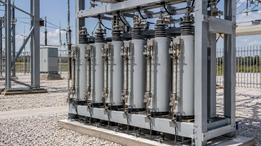
Externally fused capacitor banks isolate a failed capacitor unit with a fuse mounted where operators can inspect it. The design is easy to recognize and can keep the healthy part of a bank available, but only when unit ratings, series groups, fuse coordination, unbalance protection, switching duty, and maintenance limits are engineered together. This guide compares external, internal, and fuseless arrangements so utility and industrial buyers can ask the right design questions without treating any one architecture as universally best. Final selection belongs to the utility engineer and equipment manufacturer using the actual system study, approved standards, and owner maintenance practice.

Externally Fused Capacitor Banks: The Direct Answer
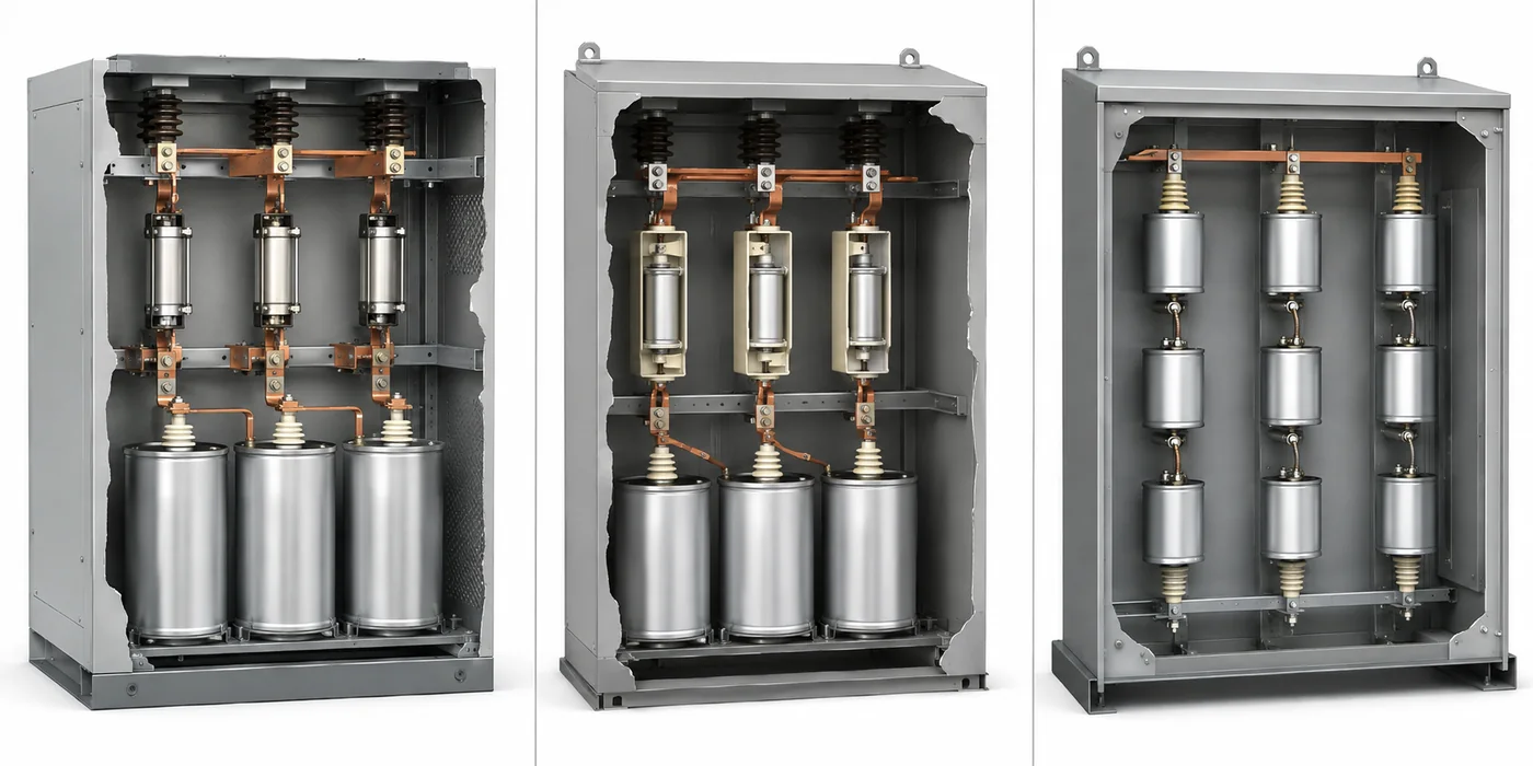
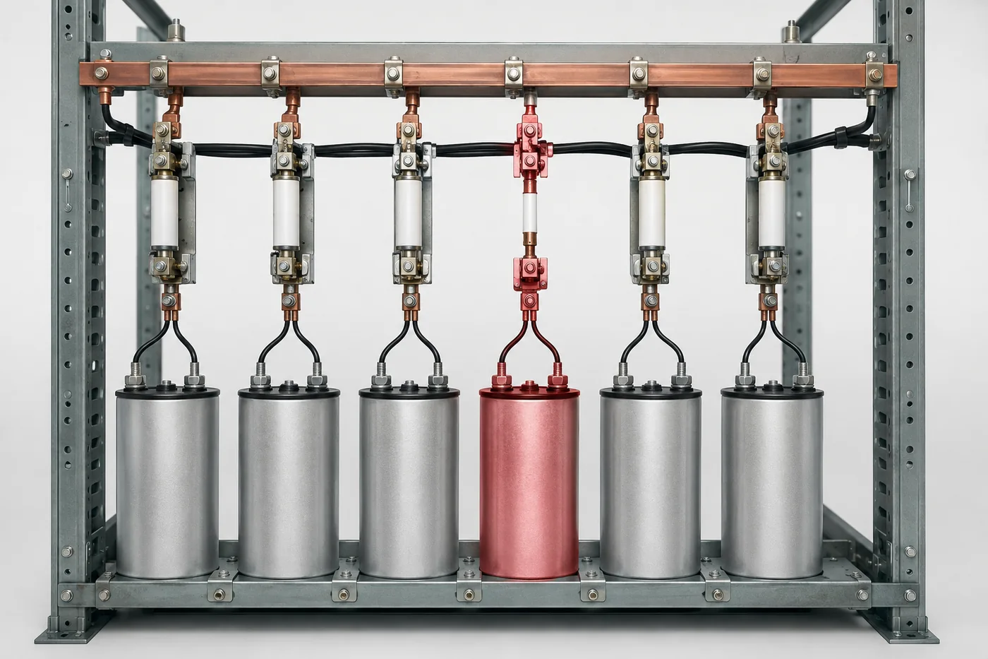
An externally fused capacitor bank uses a visible fuse in series with each capacitor unit. If a unit develops an internal fault, its fuse is intended to clear and isolate that unit while the remaining bank stays connected, subject to the bank protection and allowable voltage on the surviving units. This arrangement gives maintenance teams a clear visual indication, but it also needs space, fuse coordination, and inspection. It is one of three common utility-bank architectures; internally fused and fuseless banks distribute fault isolation differently.
Why the Fusing Architecture Matters
A shunt bank is assembled from capacitor elements, units, series groups, and phase groups. Removing one element or one complete unit changes capacitance and redistributes voltage. The acceptable change depends on the bank connection, number of series groups, neutral arrangement, protection sensitivity, and manufacturer design. That is why fusing is not an accessory choice made after the kvar rating. It is part of the electrical, mechanical, protection, and maintenance design. IEEE 1036 treats capacitor application as a coordinated study involving ratings, switching, protection, and installation rather than a one-line equipment selection.
How an External Fuse Responds to a Unit Fault
Each can is connected through its own expulsion, current-limiting, or application-specific fuse. A sufficiently severe internal fault drives fault current through that fuse. When it clears, the failed unit is disconnected. The bank does not automatically return to an ideal condition: capacitance becomes unbalanced, the neutral or bridge signal changes, and the remaining units in the affected series group may see a different voltage. Protection settings therefore need to alarm or trip before the loss of units pushes survivors beyond their permitted duty. A blown fuse is evidence to investigate, not permission to repeatedly replace fuses without finding the failed unit and checking the bank.

Externally Fused vs Internally Fused vs Fuseless
Internally fused units contain many capacitor elements, each protected by a small internal fuse. One element can be removed while much of the unit remains in service. Fuseless banks arrange elements and units so an element failure is shorted and the series-string design tolerates the resulting change until protection calls for removal. Neither option is universally superior. Externally fused designs favor visible isolation and straightforward unit replacement. Internally fused designs reduce external hardware but rely on unit construction and unbalance interpretation. Fuseless designs reduce fuse maintenance and losses, yet require enough series elements and disciplined protection engineering.
| Architecture | Fault isolation | Operational advantage | Design watch-out |
|---|---|---|---|
| Externally fused | Complete unit | Visible indication and unit replacement | External hardware, coordination, surviving-unit voltage |
| Internally fused | Individual element | Partial unit remains available | Internal fuse accumulation and unbalance interpretation |
| Fuseless | Failed element becomes part of series-string condition | No fuse maintenance or fuse losses | Requires suitable series design and sensitive protection |
Document every accepted deviation so future operators know the bank condition, remaining margin, next inspection date, and responsible engineering authority.
Protection and Unbalance Detection
Bank protection commonly considers phase overcurrent, ground or neutral quantities, overvoltage, undervoltage, and unbalance. The exact functions depend on grounded-wye, ungrounded-wye, double-wye, delta, or bridge arrangements. Unbalance protection is especially important because it can detect loss of capacitance before thermal damage becomes obvious. Settings must distinguish a real unit or element failure from system voltage unbalance, instrument-transformer error, temperature effects, and normal manufacturing tolerance. IEEE C37.99 provides guidance for protection of shunt capacitor banks, while IEEE 1036 addresses application. Project engineers should use the editions adopted by the owner and local rules.
Switching, Inrush, and Harmonic Boundaries
A fuse does not solve every capacitor-bank risk. Energization can create inrush, and back-to-back switching can be more severe when another bank is already energized on the same bus. Harmonic resonance can raise capacitor current and voltage even when no unit has failed. The study should consider available fault current, switching device capability, transient duty, discharge time, restrike risk, system harmonic spectrum, and whether reactors or filters are required. Read the related point-on-wave switching guide for controlled closing and the reactor guide for detuning context.
Inspection and Maintenance
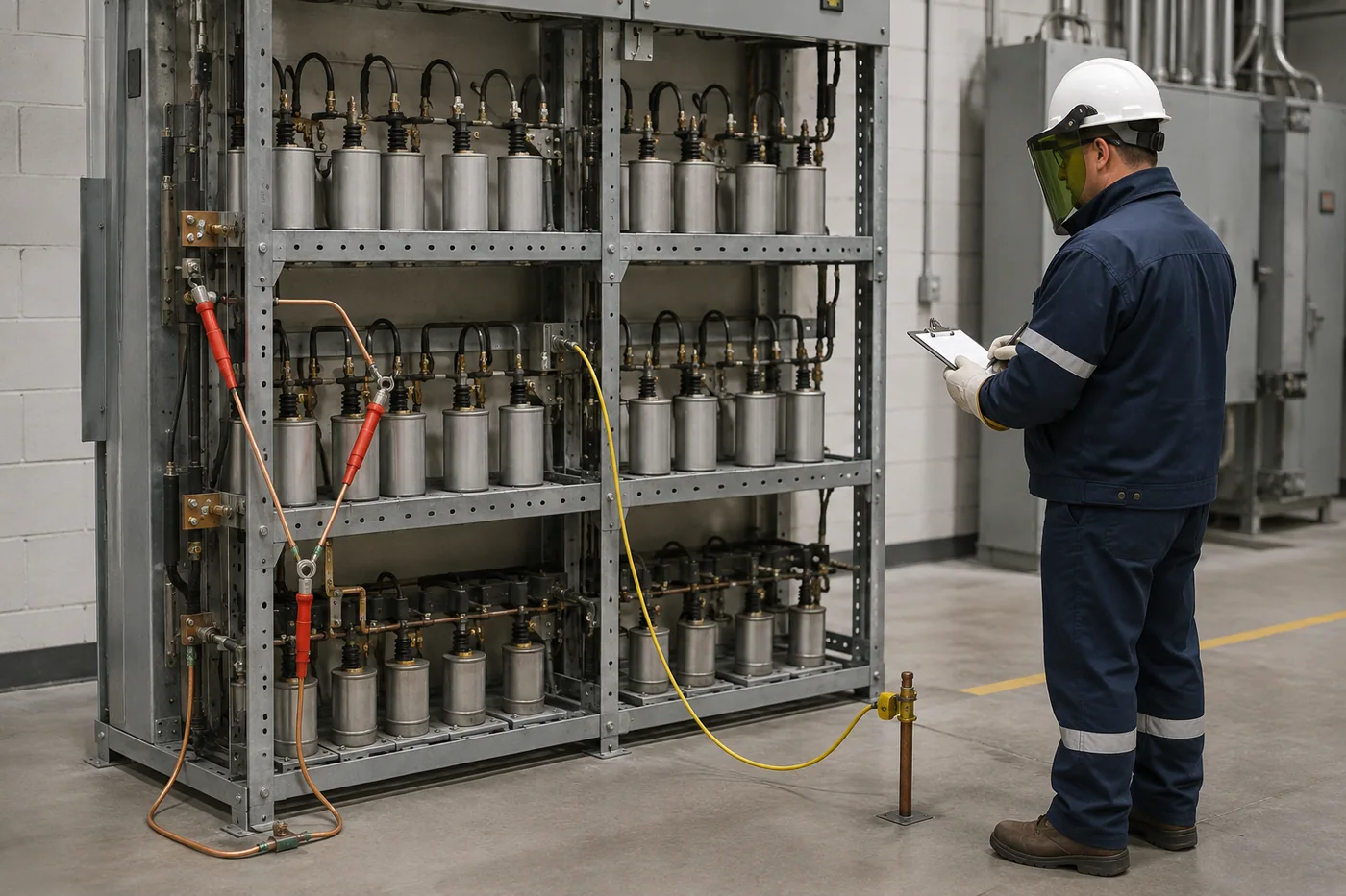
Before inspection, follow the owner’s switching order, lockout/tagout procedure, required waiting time, absence-of-voltage test, discharge verification, and grounding practice. Capacitors can retain hazardous charge after disconnection. Inspect fuse operation indicators, bushings, connections, corrosion, wildlife damage, bulging or leakage, and evidence of heating. Compare the number and location of operated fuses with relay records. Replacing only the visible fuse without testing the capacitor unit and reviewing the unbalance event can return a faulted component to service or hide a developing group problem.
Procurement Checklist
An RFQ should identify system voltage and frequency, bank kvar and step arrangement, connection and grounding, insulation level, expected ambient and altitude, available fault current, switching frequency, back-to-back conditions, harmonic study results, preferred fusing architecture, unbalance scheme, enclosure or rack requirements, creepage environment, discharge requirements, and applicable standards. Ask suppliers to state permissible failed-unit conditions and the inspection method. CNBYG low-voltage reactive-power products address plant compensation; a utility medium-voltage bank must be engineered and sourced for its own voltage class and protection scope.
Bank Connection Changes the Decision
The same fuse philosophy behaves differently in grounded-wye, ungrounded-wye, double-wye, bridge, and delta banks. A grounded neutral can provide a defined path for zero-sequence quantities, while an ungrounded arrangement requires a different method to detect phase capacitance changes. Double-wye and bridge schemes compare balanced sections and can provide sensitive unbalance measurements. The designer also checks how many parallel units are available to supply fault current into a failed unit. Too little current may not operate an external fuse as intended; too much duty can exceed the fuse or unit capability. The single-line diagram, unit arrangement, and protection calculation must therefore be reviewed together.
What Happens to the Remaining Units
When one unit is removed, the affected phase no longer has exactly the same capacitance as the healthy phases. In a series group, voltage can redistribute across the units that remain. A bank with many parallel units may tolerate one isolated unit with a relatively small change, while a compact arrangement may reach its alarm or trip limit sooner. Operators need a documented table that relates the number of isolated units to neutral current or voltage, alarm threshold, trip threshold, and maximum permitted operating time. Those limits come from the actual design; generic percentages copied from another bank are not a safe substitute.
External Fuse Selection Inputs
Fuse selection considers rated current, expected capacitor overcurrent, available fault current, energy discharge from parallel units, transient inrush, and the minimum internal fault current that must be cleared. Ambient conditions and mounting also affect performance. The fuse must tolerate normal energization and permissible harmonic current without nuisance operation, yet clear a unit fault before the case ruptures or adjacent equipment is damaged. Coordination is verified with the capacitor-unit construction and bank layout. Procurement teams should request the supplier’s time-current information and coordination basis rather than choosing a fuse solely from the capacitor nameplate current.
Commissioning Checks
Commissioning should confirm nameplates against drawings, phase and series-group placement, fuse type and orientation, torque records, clearances, grounding, discharge devices, instrument-transformer ratios, relay logic, alarm and trip paths, and the baseline unbalance value. Record capacitance measurements where the owner’s procedure requires them. A controlled first energization should be observed for abnormal sound, protection pickup, voltage step, and switching behavior. The baseline matters because future maintenance decisions are stronger when crews can compare a new event with the bank’s healthy commissioned condition instead of relying only on a visual inspection.
Perguntas frequentes
O que é um banco de condensadores com fusíveis externos?
É um banco em que cada unidade de condensador tem um fusível em série visível destinado a isolar essa unidade após uma falha interna.
Pode o banco continuar a operar depois de um fusível fundir?
Often it can temporarily, but only within the bank designer’s permitted failed-unit limits and protection settings.
Um fusível externo é sempre mais seguro?
Não. A segurança depende do projeto completo, da proteção, do procedimento de comutação, da descarga, da ligação à terra e do programa de manutenção.
Qual é a principal diferença de um banco sem fusíveis?
Um projeto sem fusíveis gere as falhas dos elementos através da sua disposição em série e proteção contra desequilíbrio, em vez de um fusível externo para cada unidade.
Should a blown fuse simply be replaced?
No. Test the associated unit, review relay records, inspect the group, and follow the owner’s approved procedure.
Referências
- IEEE 1036 — Guide for Application of Shunt Power Capacitors
- IEEE C37.99 — Guide for Protection of Shunt Capacitor Banks
