SVG Overtemperature Alarm Causes and Solutions
SVG Overtemperature Alarm Causes and Solutions
An SVG overtemperature alarm means the unit has detected a thermal condition that may reduce output or require a protective stop. Do not clear the alarm repeatedly or open the enclosure while energized. Preserve the exact code, time, load state, ambient condition and settings. Then inspect airflow, filter condition, fan operation, heat sources, current duty, voltage and cabinet design using the model-specific procedure. The cause may be installation, environment, overload, a failed cooling component or an incorrect thermal assumption.
Record the event before resetting
Capture the alarm text or code, timestamp, firmware, phase/current readings, SVG output, voltage, ambient temperature, room condition, cabinet temperature and operating mode. Note whether the alarm appears at startup, only during peak production, after a filter becomes dirty, or after a recent modification. Record whether the unit derated, tripped or returned to normal.
O Página do produto CNBYG SVG provides product context, but the exact model manual controls alarm meaning and reset sequence. Do not infer a fan or thermal threshold from a photograph or an unrelated model.
Thermal diagnostic table
| Symptom | Possible cause | Evidence to collect |
|---|---|---|
| Alarm follows high output current | Duty exceeds thermal capability, voltage condition or current-limit operation | Output current, voltage, ambient, load trend and derating state |
| Alarm rises slowly over weeks | Dusty filter, blocked vent, aging fan or rising room temperature | Airflow inspection, filter condition, fan status and seasonal data |
| Alarm occurs after cabinet retrofit | Recirculation, reduced clearance, added heat source or changed IP treatment | Before/after layout, airflow direction and cabinet heat calculation |
| One parallel module alarms first | Unequal current sharing, local obstruction, sensor issue or module fault | Per-module current, temperature, fan and alarm history |
| Alarm at startup | Fan/control supply, sensor, blocked shipping material or ambient out of range | Startup sequence, fan response, sensor status and ambient |
| Alarm after cleaning or service | Cover, filter, connector, fan direction or setting not restored | Work order, photographs, connector and settings check |
Use the table to prioritize a safe inspection. The manufacturer’s service instructions and site safety rules take precedence.
Airflow and filter checks
Inspect the external inlet and outlet without opening an energized enclosure. Confirm that walls, cable trays, covers, dust screens and adjacent equipment do not block the airflow path. Listen for abnormal fan noise and compare fan status with the model interface. If the design uses replaceable filters, follow the approved isolation and cleaning procedure. Do not blow contamination deeper into the unit.
For a rack cabinet, trace cool-air entry and warm-air exit through every module. Exhaust from one module must not return to another intake. Check roof fans, door filters, pressure drop and recirculation. For a wall unit, verify the room airflow and clearances around the enclosure. A cabinet can meet its outline dimensions and still fail its thermal path.
O Guia de requisitos de instalação do SVG e cabinet cooling checklist provide related design checks. Use SVG model heat data for the actual calculation.
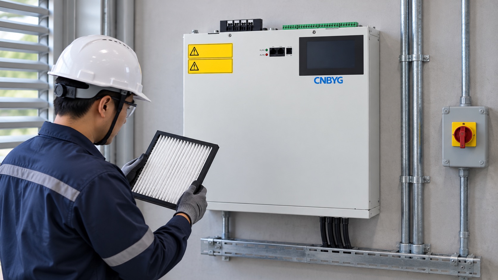
Image: illustrative external airflow inspection; it does not show energized internal service.
Check duty, voltage and ambient
Thermal stress follows real operating duty, not just the nameplate. Trend SVG output current, reactive current, enabled functions, voltage, frequency, ambient and alarm status. If reactive compensation and unbalance or harmonic functions share the converter, the combined command may increase heating. Check the model’s capability curve at the actual voltage and ambient.
Compare the alarm event with process states. A drive bank, crane cycle, welder, compressor or generator may create a short peak that the daily average misses. Record the peak and duration. If the alarm occurs only during a known overload, investigate capacity and operating policy rather than disabling the alarm.
Voltage variation can change current required for the same reactive power. Measure at the SVG terminals or defined bus, not only at a remote meter. Check phase imbalance and frequency against the model limits. An upstream transformer tap or new feeder can change thermal behavior without any SVG setting change.
Parallel modules and uneven sharing
When SVG modules operate in parallel, compare each module’s output, temperature, fan status and alarm history. One unit may carry more current because of CT/control wiring, firmware mismatch, bus impedance or a local airflow obstruction. Do not simply increase the cabinet fan speed without finding the unequal-share cause.
Check that the sharing and redundancy settings match the approved design. A disabled module can force the remaining units close to their limit. Test the loss of one unit only under an approved procedure, and record the resulting capacity and thermal state. The parallel SVG module guide covers the expansion and sharing boundary.
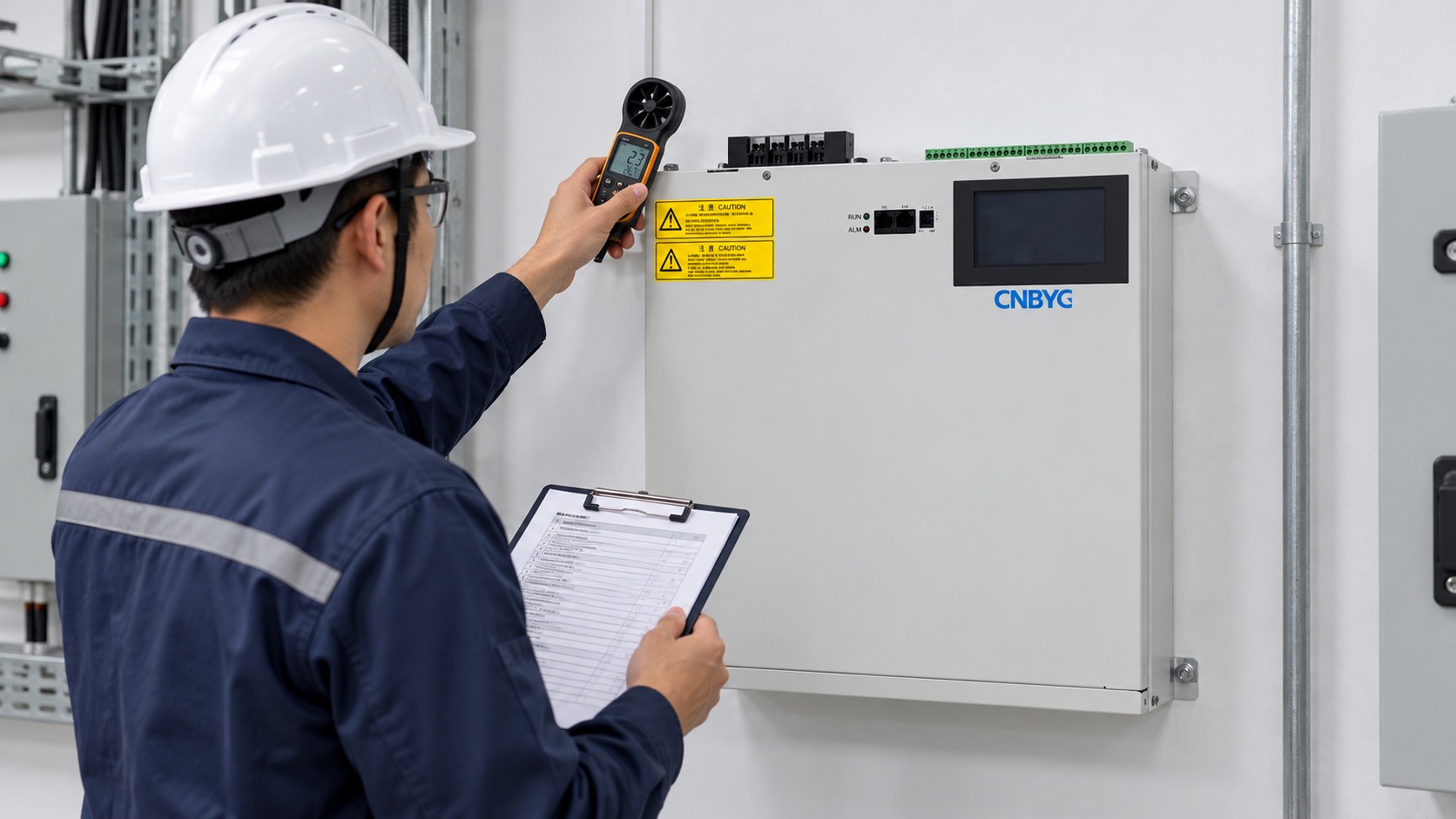
Image: illustrative module-trend review; values shown are not site data.
Cabinet and room design
Obtain model loss or heat-rejection data and calculate the room or cabinet condition at the design ambient. Include neighboring power electronics, transformers, capacitor banks, lighting and solar gain where relevant. Account for altitude, dust, moisture and filter loading. If a higher ingress-protection enclosure is selected, reassess airflow and heat removal rather than assuming the same fan arrangement remains adequate.
IEC 60529 defines degrees of enclosure protection. It does not establish a universal SVG thermal design. IEC 61439-1 gives general rules for low-voltage assemblies; apply the project-specified requirements to the completed cabinet.
Do not place the SVG near a hot exhaust, steam line or direct sun without accounting for the added ambient. Verify doors, barriers and cable entries remain closed as designed. A field-drilled opening can alter both protection and airflow.
Safe corrective sequence
Follow this order: preserve evidence; check alarm code and ambient; inspect external airflow; compare output and voltage; review fan/filter status; compare parallel modules; then perform qualified isolation and internal inspection if the manual requires it. Check connectors, fan direction, sensor, filter and settings only under the approved procedure. Replace parts with model-approved equivalents.
After correction, run the same representative load state that produced the alarm. Record temperature, output, ambient, fan status and alarms for sufficient duration. If the alarm returns, stop treating it as a reset problem. Escalate for a capacity, cabinet or component investigation.
Compare the corrected temperature trend with the original event, not with a different day. Production rate, room temperature and enabled compensation functions should be noted beside the trace. If a seasonal peak is the worst case, schedule a second observation when the room reaches that condition. A quiet commissioning day can otherwise create false confidence.
When the enclosure is opened under an approved isolation procedure, inspect connectors, fan plugs, sensor seating, filter frames and signs of contamination. Photograph the condition before cleaning or replacement. Replace only approved parts, verify fan direction and restore every cover and barrier. A repair that improves airflow but changes ingress protection or cable sealing is not complete until the enclosure is rechecked.
The maintenance plan should state who owns the daily status check, who may approve a reset, and when a qualified inspection is required. Record filter changes, fan replacements and alarm trends against the asset identifier. If the alarm repeats after two documented corrective attempts, escalate to a design or supplier review instead of extending the reset interval. A clear escalation rule protects both the equipment and the production team.
Compare a corrected temperature trend with the original event, not with a different day. Note production rate, room temperature and enabled functions beside the trace. If a seasonal peak is the worst case, schedule a second observation when the room reaches that condition. A quiet commissioning day can create false confidence.
Keep the signed corrective-action record with the equipment asset file.
Do not close the work order until the alarm history, inspection photographs, measured temperatures and approved replacement parts are attached. If the unit is part of a parallel bank, record which module alarmed and whether the remaining modules changed their current or temperature. This evidence distinguishes a local defect from a system-level loading or airflow problem.
Also record the isolation point, inspection time, ambient condition and the person who authorized the return to service. These details make the event auditable and help the service team compare alarms across shifts, seasons and production campaigns without relying on memory.
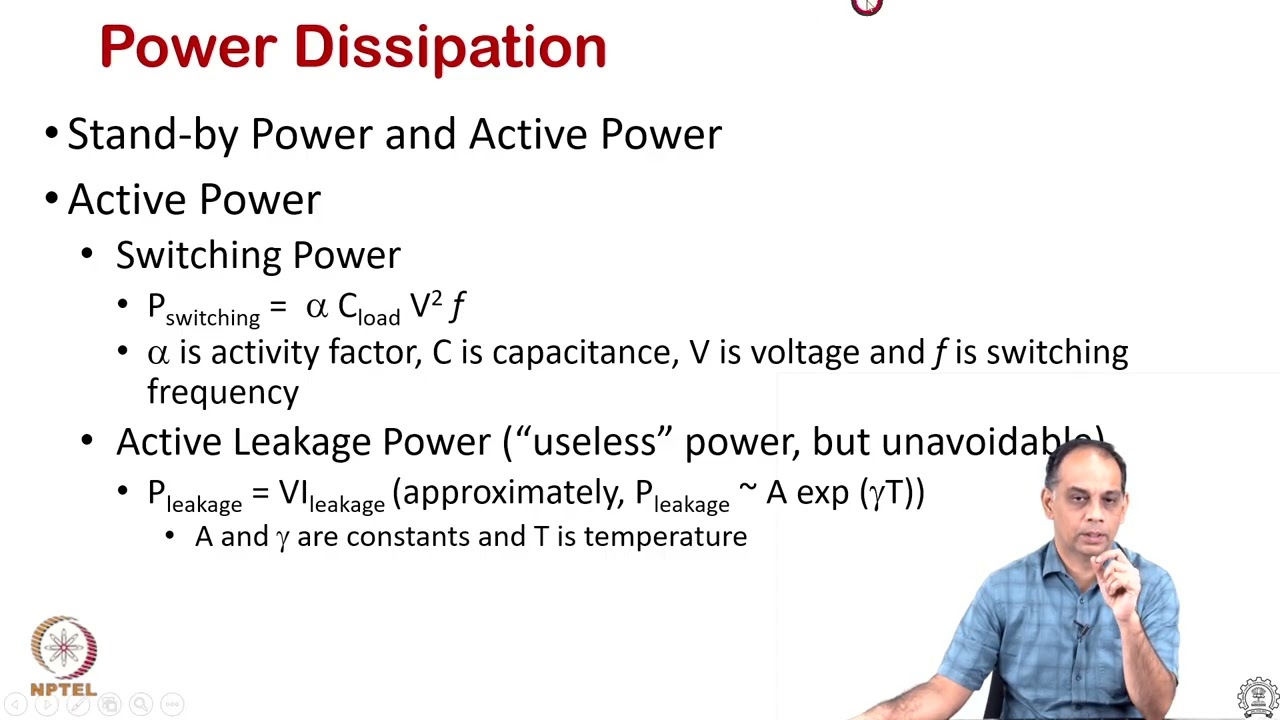
Neutral video: electronics cooling
NPTEL IIT Bombay’s lecture gives general cooling background for power-electronic equipment. It is educational context, not a model-specific service instruction.
Perguntas frequentes
Can I reset an SVG overtemperature alarm and keep running?
Only according to the model procedure and site safety program. Preserve the event and investigate the cause; repeated resets can hide a damaging condition.
Is a fan alarm the only cause of overtemperature?
No. Blocked airflow, dirty filters, high ambient, overload, voltage, uneven sharing and sensor or control faults can also contribute.
Should cabinet fan capacity be increased first?
Not automatically. Confirm airflow direction, heat load, recirculation, filter pressure drop and the model’s design limits before modifying the cabinet.
What proves the repair worked?
Repeat the triggering load case with recorded output, temperature, ambient, fan status, voltage and alarms. Save the work order and post-repair trace.
Thermal outcome
An overtemperature alarm is resolved only when the physical heat path, electrical duty and alarm evidence agree. Protect the equipment first, then use measured data to decide whether the fix is airflow, capacity, coordination or a component repair.