SVG vs Capacitor Bank for Power Factor Correction
SVG vs Capacitor Bank for Power Factor Correction
Choosing an SVG vs capacitor bank starts with the way reactive power changes. A capacitor bank is usually the simpler choice when an inductive load is stable, the required kvar can be divided into practical steps, and harmonics or resonance are controlled. A static var generator (SVG) is usually stronger when reactive demand changes quickly, fine step-free control matters, or the site alternates between inductive and capacitive operation. Neither technology is universally better. Measure the load, define the target at the correct bus, study harmonics, and compare the complete installed solution before buying.
What each device actually does
A capacitor bank supplies capacitive reactive power through fixed or switched capacitor stages. An automatic controller adds or removes steps as measured power factor changes. The method is mature and direct, but output changes in discrete increments and is related to system voltage. Switching strategy, discharge, inrush control and protection are part of the design, not optional details.
An SVG is a power-electronic compensator that measures current and produces a controlled reactive current. Within its designed capability, it can adjust continuously rather than waiting for the next capacitor step. Depending on the selected product and settings, it may compensate inductive or capacitive reactive current. Confirm the exact functions and priority logic in the model documentation rather than assuming every SVG behaves identically.
O CNBYG SVG product family provides the business connection for this comparison. A project still needs model-specific drawings, ratings and environmental data before selection.
Side-by-side selection table
The comparison below is qualitative because a defensible numeric limit must come from the selected equipment, study and project specification.
| Decision factor | Switched capacitor bank | Static var generator | Evidence to collect |
|---|---|---|---|
| Load variation | Suitable when steps can follow a stable or slowly changing demand | Useful when demand changes rapidly or frequently | Time-stamped kvar and power-factor trend by operating state |
| Control resolution | Limited by available stage sizes and switching logic | Continuously controlled within the unit’s capability | Smallest meaningful change and required settling behavior |
| Leading and lagging conditions | Capacitor stages primarily supply capacitive kvar | Selected designs can control in both directions | Minimum-load and regenerative operating records |
| Harmonic environment | Requires resonance and capacitor-duty review; detuning may be needed | Still requires voltage, harmonic and thermal compatibility checks | Voltage/current spectrum, system impedance and existing banks |
| Instalação | Stages, switching devices, protection, discharge and enclosure space | Power-electronic module, CTs, protection, cooling and controls | One-line diagram, cabinet space and heat-rejection data |
| Lifecycle work | Inspect contactors or switches, fuses, reactors and capacitor condition | Review alarms, fans, filters, electronics and firmware per manual | Site maintenance capability, spares and service response |
Why load behavior changes the answer
Start with logged fundamental current, real power, reactive power and power factor. A single handheld reading can miss the transition that drives the decision. Record production modes, large motor starts, welding cycles, lift operation, renewable generation and periods of light load. Then identify the maximum compensation requirement, the rate of change and how long each condition lasts.
If demand remains within a narrow band for long periods, a correctly staged bank can be economical and effective. If demand repeatedly moves between small and large kvar, coarse stages may hunt or leave a residual error. A smaller step improves resolution but can increase the number of switching events. The capacitor-bank step-size guide explains how stage arrangement affects control.
An SVG can follow a changing command more smoothly, but its current capacity is finite. Harmonic, unbalance or other enabled functions may share that capacity depending on the controller. The RFQ should state which function has priority and what happens at current limit.

Image: a product-referenced wall SVG during a safe installation-space review; final clearances come from the selected model.
Harmonics and resonance cannot be treated as an afterthought
Adding capacitance changes the network’s frequency response. In a plant with nonlinear loads, a bank can interact with system inductance and create or amplify a resonant condition. That does not make all capacitor banks unsuitable. It means the design needs measured harmonic data, system impedance information, and a review of detuning or filtering where applicable. The series-reactor guide describes this boundary in more detail.
IEEE 519-2022 addresses harmonic-control goals at the point of common coupling. It does not prescribe an SVG or capacitor bank. Use the applicable limits and measurement point from the project agreement, then assess the equipment at relevant load states.
An SVG also requires a harmonic compatibility check. It is power-electronic equipment with specified voltage, current, thermal and environmental limits. Do not assume it removes all harmonics merely because the term “active” appears in a brochure. If harmonic filtering is required, state that separately and verify the selected model and capacity.
Compare the complete installed scope
For a capacitor bank, include the controller, stages, contactors or other switching devices, reactors where required, fuses or breakers, discharge provisions, ventilation, enclosure and commissioning. For an SVG, include the module, CTs, protection, cabinet or wall mounting, cabling, ventilation, communications and site testing. IEC 61439-1 provides general rules for low-voltage assemblies; the actual assembly design and verification must match the project and local requirements.
Capacitor banks may have a lower equipment cost for stable duties, but price alone does not establish lifecycle value. Add expected switching-component work, capacitor condition checks, losses, cooling, spares and downtime. For an SVG, request model-specific loss and maintenance data. Do not use a generic internet efficiency claim in a financial model.
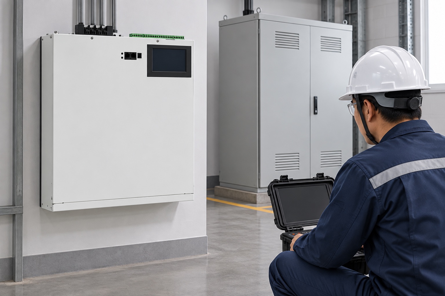
Image: illustrative performance verification; acceptance requires approved instruments, locations and comparable operating states.
Use a hybrid solution when the duty supports it
Some sites use a capacitor bank for stable base kvar and an SVG for the fast residual component. This can reduce the electronic compensation capacity while preserving fine control. It is not automatically the lowest-cost design. The controller coordination, step switching, resonance study and capacity allocation must be engineered together.
Define a dead band and ownership of the target so the SVG does not continuously counteract poorly coordinated capacitor steps. Test minimum and maximum load, step transitions, loss of a stage, and the SVG current limit. Record results at the bus where the target applies.
RFQ checklist
Send bidders the same one-line diagram, nominal voltage and frequency, grounding arrangement, transformer data, existing capacitor or filter details, and time-based load measurements. State the target power factor, measurement point, inductive and capacitive operating cases, and whether harmonic or unbalance mitigation is separate from reactive compensation.
Ask for the proposed kvar/current basis, control method, CT arrangement, protection, enclosure, cooling, expected losses, commissioning plan, warranty and exclusions. For a capacitor bank, request stage sizes and switching technology. For an SVG, request the usable reactive-current capability under the specified voltage and ambient conditions. The power-factor calculation guide can help validate the initial kvar requirement, but measured operating data should govern the final design.
Define an acceptance test before ordering
An acceptance test should reproduce agreed operating states rather than compare unrelated snapshots. Record the same measurement point, instrument setup, averaging method and process condition before and after compensation. Include a high-load case, a light-load case and any fast transition that influenced the selection. Check power factor and kvar, but also review bus voltage, capacitor-stage behavior, SVG current limit, alarms and abnormal heating.
For a bank, confirm stage sequence, discharge time, switching transients and the absence of persistent hunting. For an SVG, confirm CT polarity and phase, enabled priorities, leading/lagging behavior and response when the requested current exceeds available capacity. If both operate together, test a capacitor-step transition and demonstrate that the controllers settle without sustained counteraction.
Write the pass/fail boundary in the purchase specification. “Power factor improved” is not enough. State the target range, bus, load conditions, exclusions and duration. Preserve raw files and settings so later maintenance teams can distinguish equipment deterioration from a changed production load.
Neutral video: capacitor power-factor correction
IIT Roorkee’s lecture explains how capacitors improve power factor. It provides the foundation for the bank side of this comparison and is not a product recommendation.
Perguntas frequentes
Is an SVG always better than a capacitor bank?
No. A well-designed bank can be the practical choice for stable inductive demand. An SVG offers finer and faster control for changing or bidirectional demand, but the complete technical and lifecycle scope must be compared.
Can an SVG replace a detuned capacitor bank without a study?
No. Replacing equipment changes available kvar, control behavior and network interaction. Measure the load and harmonics, define the target, and review protection and installation requirements.
Can both technologies operate on the same bus?
Yes, if their controllers, CT locations, capacity limits and switching logic are coordinated. Commission the combined response across representative load transitions.
Which data is most important for selection?
Use time-based kW, kvar and power-factor trends; harmonic spectra; the one-line diagram; system voltage and impedance information; operating states; and the physical installation constraints.
Final decision rule
Choose the simplest verified system that meets the measured duty. Stable kvar with manageable harmonics often supports a capacitor-bank solution. Fast, fine or bidirectional compensation often supports an SVG. Mixed duty may justify a coordinated hybrid design. Require every proposal to state its assumptions and acceptance test.