

Земля принцип работы активного фильтра гармоник использует замкнутый контур управления: измеряет искаженный ток нагрузки, вычисляет выбранные нежелательные составляющие, подает команды на преобразователь мощности и вливает компенсирующий ток параллельно на определенной шине. На этой границе ток нагрузки и ток фильтра определяют ток источника, объединяя измерение, формирование опорного сигнала, отслеживание тока и параллельное вливание в единую рабочую цепь.


Что шунтирующий активный фильтр гармоник меняет в энергосистеме
Шунтовый активный фильтр гармоник подает компенсирующий ток параллельно нагрузке, уменьшая долю выбранного нежелательного тока, которая должна проходить через источник со стороны выбранной шины.
Нелинейная нагрузка потребляет ток, не пропорциональный синусоидальному напряжению питания. Например, входной выпрямитель преобразователя частоты может потреблять ток импульсами, поэтому форма волны тока нагрузки содержит основную составляющую и гармонические составляющие.
Гармонический ток — это составляющая, связанная с компонентами формы волны, превышающими основную частоту. Шунтирующий активный фильтр подает управляемый эквивалент выбранных компонентов вместо того, чтобы заставлять вышестоящий источник питания обеспечивать их все.
Шунтирующий активный фильтр гармоник представляет собой управляемый источник тока, подключенный параллельно нагрузке. Он не проводит весь ток нагрузки последовательно; он добавляет еще один путь тока на компенсируемой шине.
Ан активный фильтр гармоник, или АПФ, использует управляемую силовую электронику вместо фиксированной пассивной сети; эта статья посвящена шунтово-токовой форме.
Выберите систему знаков перед считыванием текущего значения тока. Определите ток источника и ток фильтра как втекающие в компенсируемую шину, а ток нагрузки — как вытекающий в сторону нагрузки.
i_источник + i_фильтр = i_нагрузка
Эквивалентно, i_source = i_load - i_filter. Для целевого компонента нагрузки это соглашение о ссылках на ветви присваивает фильтру тот же алгебраический знак, что и компоненту нагрузки; вычитание представляет собой локальную поставку этого компонента фильтром.
Рассмотрим несколько выпрямителей частотно-регулируемых приводов, подключенных к одной заводской шине. Приводы продолжают потреблять ток, необходимый для их технологических процессов, в то время как активный фильтр гармоник (АФГ) локально компенсирует выбранные гармонические составляющие и реактивный ток; после этого питающие кабели выше по схеме передают оставшуюся результирующую сумму на этой шине.
| Количество или функциональная задача | Что это представляет | Почему оно должно оставаться отдельным |
|---|---|---|
| Измеренный ток нагрузки | Текущий сигнал, наблюдаемый датчиком на заданной границе | Это входной сигнал контроллера, а не сама коррекция |
| Эталонный ток компенсации | Изменяющаяся во времени уставка контроллера | Там написано, что конвертер должен выдать дальше |
| Регулирование напряжения шины постоянного тока | Задача поддержания пригодного состояния постоянного тока преобразователя | Он поддерживает синтез тока, но это не инжектируемый переменный ток |
| Фактический ток фильтра | Ток, производимый импульсным преобразователем | Оно должно следовать эталону достаточно точно, чтобы влиять на шину |
| Результирующий ток источника | Сумма, видимая со стороны предложения выбранной границы | Здесь оценивается цель вознаграждения |
Измерение, команда, ток преобразователя и ток источника остаются отдельными величинами на протяжении всего принципа работы активного фильтра гармоник.
При чтении в качестве схемы активного гармонического фильтра последовательность идет от измеренного сигнала тока нагрузки к уставке контроллера, действительному току фильтра и результирующему току источника.
Шаг 1: Трансформатор тока регистрирует сигнал тока нагрузки
Трансформатор тока передает контроллеру представление тока на определенной электрической границе; сам ТТ не удаляет гармоники и не вводит корректирующий ток.
Расположение трансформаторов тока определяет, что видит контроллер. Трансформатор тока фидера и трансформатор тока главной шины представляют собой разные границы компенсации, даже если аппаратное обеспечение датчиков идентично.
Соответствие полярности и фазы сохраняет предполагаемое направление сигнала. Руководство по установке трансформаторов тока и подключению активного фильтра гармоник связывает эти решения с расчетными данными, данными о маршрутизации и пусконаладке на однолинейной схеме.
Для новичка, изучающего функциональную схему производителя, четкое различие просто: стрелка от трансформатора тока к контроллеру — это информация. Силовой путь от преобразователя к шине — это компенсирующее действие.
Шаг 2: Контроллер формирует опорный сигнал компенсационного тока
Контроллер обрабатывает измеренные электрические величины и формирует опорный сигнал компенсационного тока — целевую форму волны, которую силовая часть должна выдать на следующем этапе.
В аппаратном отношении цифровой сигнальный процессор или другой контроллер реального времени преобразует входной сигнал датчика в опорный ток. Этот опорный сигнал представляет собой команду, а не физический ток, протекающий в ветви фильтра.
Эта задача более точна, чем “обнаружение гармоник”. Контроллер должен различать компоненты тока, связанные с его настроенной задачей, формировать опорный сигнал с требуемым знаком и постоянно обновлять команду по мере изменения нагрузки.
В различных конструкциях могут использоваться методы синхронной системы координат, мгновенные методы p-q, спектральный анализ или другая архитектура управления. Эти названия алгоритмов описывают способы расчета целевого значения; они не меняют общую функциональную последовательность измерений, формирования опорного сигнала и отслеживания тока.
Инженер, сравнивающий одну блок-схему с надписью dq0 с другой с ярлыком п-q поэтому следует задать два отдельных вопроса. Какая текущая задача рассчитывается и как преобразователь отслеживает эту уставку в ожидаемых условиях нагрузки и питания?
Оценка сигнала компенсации, регулирование напряжения шины постоянного тока и управление током преобразователя — это связанные, но разные задачи. Вместе они составляют принцип работы активного фильтра мощности, даже если внутренний алгоритм и аппаратная реализация различаются.
Шаг 3: Шина постоянного тока и IGBT-преобразователь формируют ток фильтра
Управление шиной постоянного тока поддерживает переключаемый преобразователь, который преобразует цифровое задание в реальный ток фильтра переменного тока на компенсируемой шине.
Шина постоянного тока — это регулируемый внутренний энергетический буфер преобразователя. Она обеспечивает силовой каскад необходимым электрическим запасом по напряжению для формирования тока, в то время как отдельная функция управления поддерживает напряжение в цепи постоянного тока на уровне заданного рабочего значения.
Инвертор на IGBT — это не просто электронный выключатель для шкафа. Его полупроводниковые плечи переключаются под управлением тока, благодаря чему выходной сигнал преобразователя следует за изменяющейся командой тока компенсации.
Именно поэтому утверждение о том, что активный фильтр гармоник “запасает гармоники”, формирует неправильное представление. Контроллер оценивает желаемый ток, а преобразователь непрерывно обменивается электрической энергией с сетью переменного тока в процессе синтеза этого тока; здесь нет никакого «хранилища» пойманных форм волн гармоник, ожидающих своего опустошения.
Текущее отслеживание замыкает контур между командой и действием. Контроллер наблюдает за электрическим откликом, настраивает переключение преобразователя и обновляет команду по мере изменения нелинейной нагрузки, благодаря чему фактический ток фильтра следует за опорным сигналом, а не остается фиксированной формы волны.
Шаг 4: Ток фильтра и ток нагрузки добавляются на выбранной шине
При всех стрелках ветвей, направленных так, как определено выше, компенсация происходит посредством суммирования токов на выбранном узле: фильтр воспроизводит выбранные составляющие тока нагрузки с тем же алгебраическим знаком, поэтому вычитание тока фильтра уменьшает их вклад в ток источника.
Предположим, что ток нагрузки содержит основную составляющую и несколько гармонических составляющих. Источник по-прежнему обеспечивает мощность основной частоты, требуемую технологическим процессом, но ветвь фильтра может нести управляемый эквивалент выбранных нежелательных составляющих.
Знакомая фраза “равные и противоположные” предполагает, что токи нагрузки и фильтра строятся с использованием одного общего глобального опорного направления. Согласно принятому здесь правилу ветвевых опорных направлений, оба значения компонентов имеют одинаковый алгебраический знак, поскольку стрелки ветвей нагрузки и фильтра указывают в противоположных направлениях относительно шины.
Точка общего присоединения, или ТОП, — это согласованная электрическая граница, на которой оценивается соотношение между токами источника, нагрузки и фильтра. Простым языком, это шина, где возникает вопрос: какой ток теперь видит источник питания?
Текущий баланс также отвечает на распространенный вопрос сообщества о том, куда деваются гармоники. Фильтр не переносит накопленный пакет искажений куда-то еще; он генерирует контролируемый ток, чьи выбранные составляющие уменьшают соответствующие составляющие в суммарном токе со стороны источника.
При изменении нагрузки измеряемая форма сигнала меняется, опорное значение пересчитывается, и выходной сигнал преобразователя следует за ним. Динамическое обновление является определяющим отличием между управляемым источником активного тока и фиксированной настроенной цепью.

Почему активное подавление отличается от пассивной фильтрации
Активные и пассивные гармонические фильтры действуют посредством различных физических механизмов: АГФ измеряет и генерирует изменяющийся ток, в то время как пассивный фильтр использует катушки индуктивности, конденсаторы и сопротивление для создания путей с импедансом, зависящим от частоты.
Это различие разрешает знакомый вопрос: “Являются ли гармонические фильтры одновременно конденсаторными батареями?”Батарея конденсаторов может вырабатывать реактивную мощность, а настроенный пассивный фильтр может включать в себя конденсаторы, но ни то, ни другое автоматически не становится описанным выше управляемым преобразователем.
| Точка сравнения | Шунтовый активный фильтр гармоник | Настроенный пассивный гармонический фильтр |
|---|---|---|
| Подключение и действие | Подключается параллельно и инжектирует заданный ток | Обеспечивает частотно-зависимый путь импеданса с помощью пассивных компонентов |
| Реакция на изменяющуюся нагрузку | Пересчитывает и отслеживает изменяющийся опорный ток | Его настройка определяется номиналами компонентов и взаимодействием системы |
| Главная регулируемая величина | Ток преобразователя следует за рассчитанным эталонным значением | Сетевой импеданс формирует путь выбранных частот |
| Основная проектная зависимость | Граница измерения, цель контроллера, текущая емкость, динамика преобразователя и интеграция | Частота настройки, номиналы компонентов, импеданс цепи, резонанс и условия коммутации |
Активное и пассивное оборудование также может быть согласовано на одном объекте, поскольку каждое из них действует посредством другого электрического механизма.
Для принятия полного решения по выбору, включая настройку, резонанс, поведение при изменении нагрузки и компромиссы при установке, используйте активный фильтр гармоник против пассивного фильтра гармоник.
Чего не гарантирует “равное и противоположное”
“Равные и противоположные” описывают соотношение физических компонентов, когда оба тока имеют одно общее опорное направление; это не алгебраическое правило для стрелок ветвей, используемое выше. Остаточные искажения по-прежнему зависят от измерения, доступного компенсирующего тока, отклика контроллера, состояния сети и состояния нагрузки.
Показания прибора меняются в зависимости от точки измерения и режима работы. Поэтому результат на одной панели не применим к другой точке общего присоединения (PCC) или другому режиму нагрузки.
Важно: Более низкое значение тока гармоник на одной панели не является доказательством того, что выбор места установки трансформатора тока, емкость фильтра или целевой показатель приемки в точке общего присоединения (PCC) были окончательно согласованы: увяжите этот результат с определенной границей измерений, репрезентативным рабочим состоянием, доступным компенсирующим током и согласованным методом приемки.
Коэффициент нелинейных искажений (THD) представляет собой удобную сводную характеристику гармонического состава формы сигнала. Он не является самостоятельным ответом на вопрос о том, где должен располагаться трансформатор тока, какой номинальный ток требуется или соблюден ли договорной предел.
Используйте Руководство по установке и подключению трансформаторов тока (ТТ) определить границу измерения/управления, прежде чем считать показание репрезентативным. Как только эта граница установлена, Руководство по расчету размеров АПФ преобразует измеренный спрос в исходные данные по мощности, а Руководство по выбору AHF применяет эти входные данные к оборудованию и критериям приемки.
Корректная модель контура управления не предоставляет данные объекта, необходимые для выбора оборудования. Репрезентативные журналы, однолинейная схема, монтажные ограничения и определенная точка приемки завершают это следующее решение.
Как семейство продуктов CNBYG AHF/APF реализует цепь
Семейство продукции CNBYG AHF/APF реализует ту же функциональную цепочку, описанную выше: внешнее измерение тока с помощью трансформаторов тока, цифровое выделение целевых составляющих тока, а также генерацию и впрыск компенсационного тока на базе IGBT.
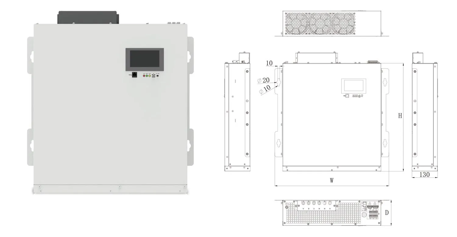
Земля Семейство продуктов CNBYG AHF/APF представляет исполнения для настенного монтажа и установки в стойку. В этих исполнениях внешний вход трансформатора тока подается на цифровую обработку, которая управляет инверторным током, впрыскиваемым в шину.
Перед сравнением серии или номинала CNBYG определите электрическую границу, типичный профиль гармонических токов, напряжение и конфигурацию системы, состояния нагрузки, существующее компенсационное оборудование, условия установки и целевые показатели приемки.
Земля Система качества электроэнергии Хаб систематизирует контекст измерений и системные данные, используемые до выбора оборудования. Руководства по трансформаторам тока, расчету и подбору обеспечивают следующий уровень детализации после завершения этой записи.
Часто задаваемые вопросы
Как работает активный фильтр гармоник пошагово: 1. Измерение тока нагрузки: Трансформаторы тока (ТТ) непрерывно измеряют полный ток нагрузки, который содержит как основную частоту (например, 50 или 60 Гц), так и нежелательные гармонические составляющие. 2. Анализ и обнаружение гармоник: Сигнал тока поступает в цифровой сигнальный процессор (DSP) или контроллер. Блок управления использует алгоритмы (такие как быстрое преобразование Фурье — БПФ или метод мгновенной реактивной мощности) для выделения и разделения токов гармоник и реактивной мощности от основной волны тока. 3. Генерация компенсирующего сигнала: На основе полученного анализа контроллер рассчитывает точную форму и фазу инверсного тока (противофазного), необходимого для полной нейтрализации обнаруженных гармоник. Этот сигнал отправляется на силовой инвертор. 4. Инвертирование и подача компенсации: Инвертор, построенный на IGBT-транзисторах и питающийся от шины постоянного тока, мгновенно преобразует этот расчетный сигнал в реальный компенсирующий ток. 5. Впрыск в энергосистему: Сгенерированный компенсирующий ток подается обратно в электрическую сеть в точке подключения (обычно параллельно нагрузке). 6. Успешная фильтрация: В соответствии с законом Кирхгофа, инвертированный ток встречается с гармониками нагрузки. Поскольку компенсирующий ток находится строго в противофазе (сдвинут на 180 градусов), происходит их взаимное уничтожение (деструктивная интерференция). 7. Результат: В результате в питающую сеть возвращается практически чистый синусоидальный ток основной частоты, а гармоники устраняются в режиме реального времени (обычно за микросекунды). Весь процесс происходит непрерывно и адаптируется к изменениям нагрузки.
Он измеряет ток на заданной границе, обрабатывает сигнал в опорный сигнал компенсирующего тока, использует управляемый преобразователь для получения тока фильтра, инжектирует этот ток параллельно и обновляет команду по мере изменения нагрузки. При токах источника и фильтра, направленных к шине, источник обеспечивает ток нагрузки за вычетом вклада фильтра.
В чем разница между пассивным и активным фильтром гармоник?
Пассивный фильтр использует настроенные индуктивности, конденсаторы и сопротивление для формирования импеданса сети на выбранных частотах. Активный фильтр измеряет электрическое состояние и дает команду преобразователю мощности генерировать изменяющийся компенсационный ток.
Почему компенсирующий ток называют равным и противоположным?
В этой фразе используется одно общее глобальное опорное направление, при котором физический компонент фильтра противоположен целевому компоненту нагрузки. При использовании стрелок ветвей в данной статье компонент фильтра является копией целевого компонента нагрузки с тем же знаком, и i_source = i_load - i_filter вычитает его из исходного тока.
Устраняет ли активный фильтр гармоник (AHF) все гармоники?
Из одного только принципа не следует универсальный результат. Остаточный ток зависит от границы измерения, целевых компонентов, доступной токовой емкости, реакции контроллера и преобразователя, состояния нагрузки и системной интеграции.
Где подключается активный гармонический фильтр?
Общий шунтирующий активный фильтр гармоник (АФГ) подключается параллельно с нагрузкой или шиной для введения тока. Точная точка подключения и расположение трансформатора тока должны соответствовать предполагаемой границе компенсации и утвержденному проектному решению.
Каковы четыре типа активных фильтров?
Общая высокоуровневая классификация включает параллельные, последовательные, гибридные кондиционеры и кондиционеры качества электроэнергии с единой структурой (UPQC). Параллельные фильтры в основном инжектируют ток параллельно, последовательные фильтры инжектируют напряжение, гибридные схемы объединяют активные и пассивные функции, а UPQC координирует последовательные и параллельные функции.
Может ли активный фильтр гармонок (AHF) также корректировать коэффициент мощности?
Некоторые изделия с активными фильтрами могут включать компенсацию реактивного тока или коррекцию коэффициента мощности в качестве настраиваемой функции. Доступность этой функции и распределение мощности должны быть подтверждены для выбранного изделия и области применения.
Как рассчитывается размер АФФ и какова его стоимость?
Выбор номинала начинается с репрезентативного измеренного спроса на гармонический ток на предполагаемой границе раздела, после чего учитываются напряжение, состояние нагрузки, топология, монтаж, тепловые условия и цель приемки. Стоимость определяется требуемой емкостью оборудования и интеграцией проекта, а не только схемой рабочего принципа; для принятия этого решения используйте связанные руководства по выбору и расчету номинала.