


How to Set Harmonic Compensation Priorities in an AHF
An active harmonic filter (AHF) should not be configured by turning every compensation option to its maximum. Start with a measured load profile and a clearly defined observation point. Give priority to the harmonic orders that contribute the most current at that point, while reserving enough filter current for load changes and any separately required reactive-power or phase-balancing function. Confirm the current-transformer (CT) arrangement and operating mode before changing settings. Then compare measurements made under equivalent load conditions, at the same location, before and after each change. A lower number on one screen is not proof that the whole installation is compliant.
This is a commissioning decision, not a universal set of menu values. The actual controls, harmonic-order range, current limits and selectable functions depend on the model and its firmware. Use the approved manual for the installed unit and have a qualified electrical professional perform any work on energized equipment. The method below helps you decide what to prioritize и how to verify it without pretending that one preset fits every site.
First define the result you are trying to improve
An AHF measures current and injects an opposing current so that the upstream source supplies less of the unwanted component. The practical target may be harmonic current at a feeder, distortion seen by a transformer, or a power-quality objective at the point of common coupling (PCC). Those are not necessarily the same measurement point. The IEEE 519-2022 standard locates its harmonic-control design goals at the PCC, where the installation interfaces with the supply. A feeder-level improvement may be valuable but does not by itself establish a PCC result.
Write down three things before touching a setting: the protected equipment or business problem, the measurement point, and the acceptance criterion. For example, an engineer may be trying to reduce fifth- and seventh-order current on a VFD feeder to relieve a transformer. Another site may be investigating high voltage distortion at its PCC. The measurements, filter location and required capacity may differ. Do not replace a site-specific engineering study with a generic percentage-THD promise.
Current THD is a ratio to the fundamental current. Under a light load, the percentage can rise even while the absolute harmonic current falls. For commissioning, preserve the harmonic spectrum in amperes, fundamental current, total RMS current, voltage distortion, loading and time stamps. This prevents a well-intended adjustment from being judged by an isolated percentage.
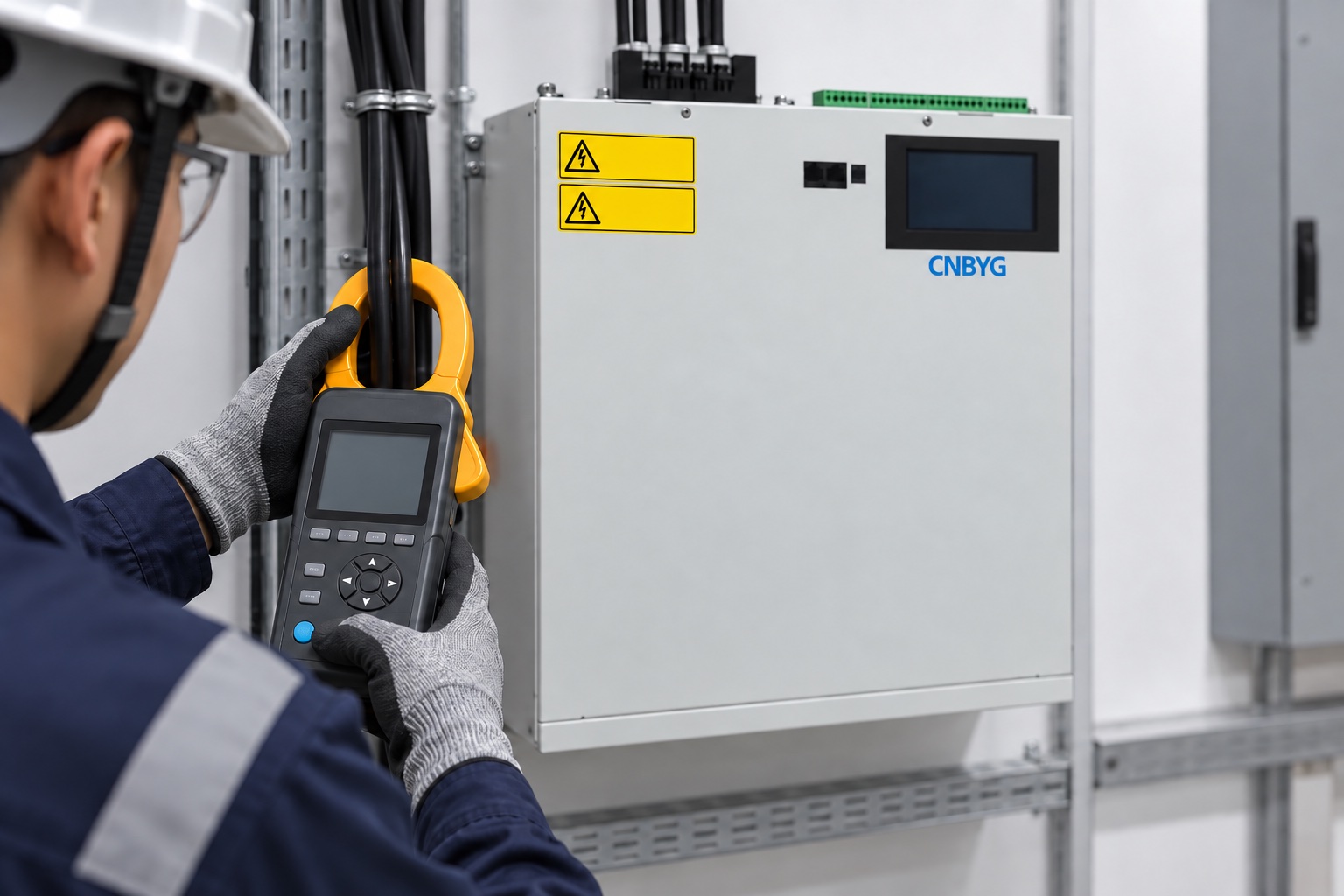

Image: baseline measurement near a product-referenced AHF cabinet; the pictured instrument reading is illustrative, not site data.
Build a repeatable baseline, not a single snapshot
Log the installation in several representative states: low production, typical production, peak demand, and known transitions such as large drive starts or capacitor-stage changes. Record which loads are running and whether an existing power-factor controller or capacitor bank changes state. If the problem is intermittent, a one-minute screenshot taken at a quiet time is insufficient.
Use an analyzer and measurement method appropriate to the contractual objective. IEC 61000-4-30:2025 specifies methods for measuring and interpreting power-quality parameters, including harmonic voltage and current; IEC 61000-4-7 addresses harmonic and interharmonic measurement instrumentation. These documents do not prescribe the best AHF menu setting. They help ensure that before/after data is comparable and meaningful.
Record the CT locations, phase identification, CT ratios, system voltage and wiring arrangement in the same baseline package. A wrong CT polarity or ratio can make a healthy filter respond to the wrong magnitude or direction of current. Before treating an order as a low priority, verify that the measurement is credible. The AHF installation checklist covers the placement and pre-energization checks; the commissioning procedure covers a broader startup sequence. This article addresses the narrower question of allocating compensation effort once that foundation is sound.
Identify the harmonic orders that actually dominate
Many industrial nonlinear loads create a few prominent orders rather than a flat spectrum. Do not assume the usual orders are dominant at your site. Sort the measured individual harmonic currents in amperes for the same operating period, and compare their contribution to the total distortion current. Check each phase and, in four-wire systems, the neutral-related behavior as appropriate. A spectrum from one phase can hide another phase’s problem.
When the filter offers selective-order settings, start with the measured orders that produce a meaningful upstream reduction and are within the installed unit’s supported range. Consider both the magnitude and the persistence of each order. A small, short-lived component may not deserve the same priority as a substantial component present throughout the production shift. If the control only offers an aggregate harmonic mode, the commissioning decision becomes current allocation and mode selection rather than individual-order ranking.
The table below is a decision aid, not a factory setting or compliance threshold.
| Observed condition | Initial priority | Reason to verify |
|---|---|---|
| One or two orders account for most measured harmonic current across normal shifts | Prioritize those orders, if selective control is supported | Compare their upstream amperes before and after, under matching load |
| Several orders rise together only during a specific process | Include the process state in the test; do not tune from idle data | Confirm the AHF has current headroom during the actual event |
| Harmonic current is moderate, but displacement power factor also needs correction | Allocate capacity deliberately between harmonics and reactive current | Check that one function is not starving the other at peak load |
| One phase or neutral path is unusually stressed | Review wiring, CTs and phase/neutral current before changing priorities | Do not mask a measurement or topology problem with a setting |
| Current THD percentage increases when production is idle | Inspect absolute harmonic current and fundamental current | The percentage may change mainly because the denominator changed |
Reserve current for the functions the site actually needs
An AHF has a finite output-current capability. If the same unit is asked to provide harmonic correction, reactive compensation and load balancing, those demands can coincide. The best operating priority depends on the site’s goal and the model’s documented control behavior. Do not assume that checking three functions in a menu guarantees full performance from all three at once.
Ask the commissioning team to compare the worst representative demand against the available continuous capacity and any manufacturer-specified derating. If the harmonic spectrum requires most of the available current during a high-load shift, a reactive-power target may need its own solution or a differently sized system. Conversely, if harmonics are modest and power factor is the contractual driver, the allocation may differ. The AHF sizing guide for VFD loads helps frame capacity; this page focuses on priority after sizing.
Also distinguish power-factor improvement from harmonic reduction. A capacitor bank or SVG system may be suitable for a reactive-power objective, but it is not a substitute for verifying harmonic behavior. Where capacitor stages operate on the same bus, review their switching states and resonance risk as part of the study. A filter setting should not be used to conceal an unresolved resonance or installation problem.
Apply one change at a time and document it
Once baseline data and the control manual are available, record the existing configuration before editing anything. Take a configuration export or dated photographs of the relevant screens if the installed equipment permits it. Change only one priority-related parameter or operating mode at a time. Note the exact model, firmware, old value, new value, author, date, load state and reason. That record makes a reversal possible if the result is worse.
After each change, allow the system to settle and measure over an appropriate interval for the load pattern. Do not interpret a transient start-up trace as steady operation. Recheck filter output current, warnings, temperature or derating indication, and the relevant upstream spectrum. If a new order rises or the unit hits its current ceiling, stop and investigate rather than repeatedly increasing compensation requests. The correct next action may be relocation, CT correction, capacity review or an upstream network study—not another menu change.
Земля CNBYG active harmonic filter product page can be used to identify the relevant product family and request model-specific documentation. Do not infer a particular selectable order, threshold or performance guarantee from a general product photograph.
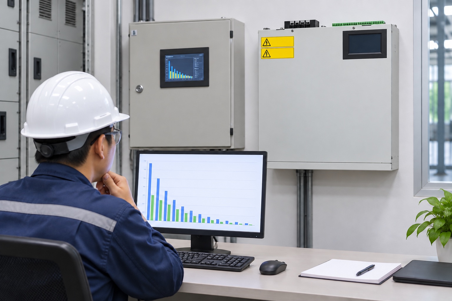
Image: review workflow with a CNBYG AHF-referenced cabinet; the charts are illustrative and contain no project claim.
Compare like with like at both the feeder and the PCC
Validation should match the original goal. Keep the analyzer at the same electrical point, with the same probe orientation and comparable load state. Compare individual harmonic current in amperes, total harmonic current, voltage distortion, filter output current and production state. Where a PCC requirement applies, measure there too; a good local feeder result can be diluted or offset by other site loads.
When reporting a result, show the measurement interval and operating conditions instead of one best-looking value. If a site’s goal refers to a standard or utility agreement, have the engineer apply its specified method, measurement point and averaging rules. A dashboard percentage alone is not a compliance certificate. For a deeper explanation of the sensing and injection mechanism, see the active harmonic filter working-principle guide; for a structured before/after log, see the APF and SVG comparison method.
What if a higher priority makes performance worse?
First compare the new test with the baseline load state. Then inspect whether the AHF is at its output-current limit, whether CT configuration and polarity are correct, and whether other compensation equipment changed state. Check for an alarm, an unsupported order or a model-specific control interaction. If the source of the deterioration is not evident, restore the recorded prior configuration under the approved procedure and escalate to the equipment supplier or site engineer. Avoid repeated live trial-and-error on an industrial distribution system.
Electrical access and isolation requirements are site- and jurisdiction-specific. In the US, OSHA 29 CFR 1910.333 covers work practices for electrical safety. This article is a planning and measurement guide, not authorization to work on energized conductors.
Watch the principle in a neutral teaching source
IIT Roorkee’s lecture, Shunt Active Power Filter, explains the current-sensing and compensating-current principle behind the control decision. It is background education, not a setup tutorial for this product.

Часто задаваемые вопросы
Should every available harmonic order be enabled?
Not automatically. Start with the site’s measured spectrum and the installed unit’s documented capabilities. Where selective control is available, prioritize the orders that materially affect the defined measurement point; where it is not, manage the available current and operating mode. Verify the result rather than assuming more selected orders always mean better performance.
Can the filter prioritize harmonics and reactive power at the same time?
Some products can perform multiple functions, but the available output current remains finite. Check the exact model’s control logic and capacity under the site’s peak combined demand. If one objective loses performance, separate the duties or revisit sizing rather than claiming both are fully satisfied.
Which number proves that the settings worked?
No single number does. Use comparable load periods and the original observation point. Preserve individual harmonic current, fundamental current, current and voltage distortion, output current and any site-specific compliance metric. If the goal is at the PCC, a feeder display alone is insufficient.
When should settings not be changed?
Pause when CT orientation or ratio is uncertain, when the measurement point is undefined, when baseline data is missing, when the unit has active alarms, or when the safe-work procedure and model manual are unavailable. Correct those prerequisites first.
A practical handover record
The finished commissioning package should include a one-line diagram with CT and AHF locations, baseline and final time-series, order-by-order spectra in amperes, load-state notes, the installed product and firmware identification, a settings change log, current-capacity observations, unresolved exceptions and the next review date. This record is more valuable than a screenshot labeled “THD improved” because another engineer can reproduce the judgment when loads or utility conditions change.