


APFC panel protection should decide whether compensation is permitted before the controller decides how much compensation to add. Interlocking connects the demand command with supply status, measurement validity, capacitor eligibility and protective conditions. A high reactive-power demand must not override a blocked stage, an unsafe operating mode or a protection trip.
This guide explains how to build and verify a cause-and-effect plan for an automatic capacitor bank. It is not a universal relay circuit or a list of fixed settings. Actual thresholds, wiring, reset behavior and protective devices require the approved panel design, equipment instructions and applicable installation rules.
Separate demand control from permission to operate
The APFC controller estimates the compensation required from its measurement inputs. A stage can satisfy that demand only if it is available and eligible. Keeping these decisions distinct makes the system easier to diagnose: the controller can request compensation while an interlock correctly prevents switching.
An interlock may be implemented through controller logic, a hardwired enable, an external protective device or several coordinated layers. The physical implementation matters because each layer behaves differently when power is lost, a wire breaks or a communication link fails. Document what actually blocks operation rather than writing only “protection provided.”
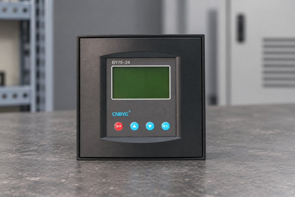
Земля CNBYG BY75 reactive-power compensation controller is a relevant control product, but its available functions must be checked in the exact model documentation. Do not assume that every protection discussed here is built into the controller. Some conditions require external equipment or a panel-level design decision.
Define the operating modes
List normal utility operation, generator operation, transfer, maintenance, manual control and restart. Identify the required compensation behavior in each mode. A bank allowed on the utility supply may need different restrictions when the source impedance, capacity or control objective changes.
For source transfer, determine what happens to stage commands and eligibility timers. The system should not rely on undocumented assumptions about a short power interruption. A controller restart can erase volatile state, while a capacitor may still retain charge. The restart sequence must therefore be explicitly designed and tested.
Manual mode also needs a clear definition. Determine which protective blocks remain active and who may authorize operation. Manual selection should not turn a protection function into an optional warning unless the approved design and procedure explicitly account for that behavior.
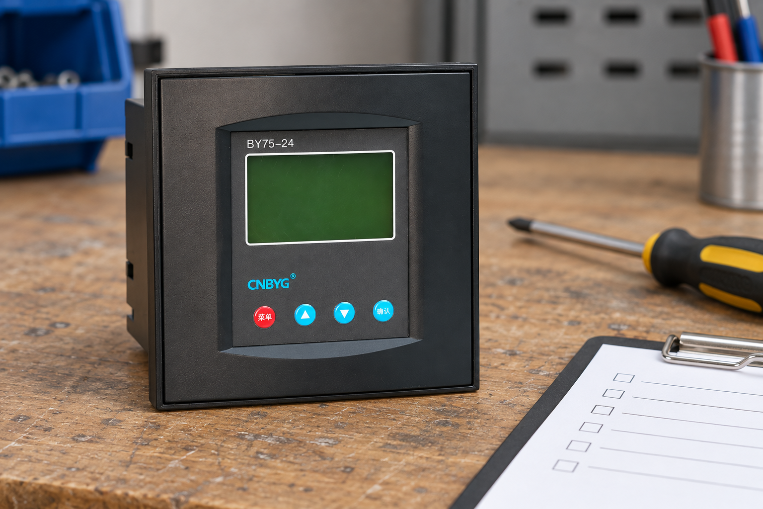

Reference-based illustration. The actual interlock circuit and available controller functions are model-specific.
Build a cause-and-effect schedule
| Состояние | Required design question | Verification evidence |
|---|---|---|
| Supply lost or transferred | Are stage commands removed and restart conditions enforced? | Approved transfer and restart test record |
| Measurement invalid | Does the bank stop making decisions from unreliable data? | Input-failure behavior and alarm record |
| Stage recently disconnected | Is that same stage blocked until eligible? | Individual-stage state and timing evidence |
| Thermal condition exceeded | Which stages are removed and how is reset controlled? | Sensor mapping and specified functional test |
| Protective device operated | Can automatic commands continue to a failed circuit? | Trip indication, stage availability and reset check |
| Feedback disagrees with command | Is the disagreement detected and escalated? | Command-versus-feedback event record |
| Manual mode selected | Which protective permissions remain mandatory? | Mode test and operating procedure |
These are qualitative design checks. They intentionally omit universal temperatures, voltages and delay values. The acceptance criteria must be derived from the actual equipment and the approved project requirements, with a documented reason for each setting.
Protect capacitor reconnection eligibility
A delay between any two output commands is different from a delay protecting the same capacitor stage from premature reconnection. The logic should recognize when each stage was removed and when it may return. Changing the stage order must not defeat that requirement.
Use the manufacturer’s discharge characteristics and the bank design to establish eligibility. Consider what happens if control power fails or the controller restarts. A timer that restarts at zero or forgets the previous stage state may need a conservative startup block or another approved safeguard.
Земля capacitor switching delay guide explains the distinction between operating pace and capacitor state. Do not reduce a protection-related delay simply to improve the displayed power factor. If demand changes faster than the bank can safely respond, reassess the application and switching technology.
cURL Too many subrequests by single Worker invocation. To configure this limit, refer to https://developers.cloudflare.com/workers/wrangler/configuration/#limits
cURL Too many subrequests by single Worker invocation. To configure this limit, refer to https://developers.cloudflare.com/workers/wrangler/configuration/#limits.
cURL Too many subrequests by single Worker invocation. To configure this limit, refer to https://developers.cloudflare.com/workers/wrangler/configuration/#limits.
cURL Too many subrequests by single Worker invocation. To configure this limit, refer to https://developers.cloudflare.com/workers/wrangler/configuration/#limits cURL Too many subrequests by single Worker invocation. To configure this limit, refer to https://developers.cloudflare.com/workers/wrangler/configuration/#limits cURL Too many subrequests by single Worker invocation. To configure this limit, refer to https://developers.cloudflare.com/workers/wrangler/configuration/#limits.
cURL Too many subrequests by single Worker invocation. To configure this limit, refer to https://developers.cloudflare.com/workers/wrangler/configuration/#limits
cURL Too many subrequests by single Worker invocation. To configure this limit, refer to https://developers.cloudflare.com/workers/wrangler/configuration/#limits.
cURL Too many subrequests by single Worker invocation. To configure this limit, refer to https://developers.cloudflare.com/workers/wrangler/configuration/#limits.
Земля power factor correction standards guide helps organize utility, equipment and installation requirements. Cite the relevant project specification and exact equipment documents when assigning acceptance criteria; do not convert a general article into a protective-device coordination study.
Detect command and response disagreement
A command does not prove that a capacitor stage is connected, and removal of a command does not prove that the power path has opened. Depending on the design, feedback contacts or suitable measurements may be needed to establish actual stage behavior. Define what each signal means and its limitations.
Where a stage response is inferred from reactive-power change, consider the simultaneous load changes that can obscure it. A large production load starting during the test can mask the expected step. The test conditions and measurement boundary should make the result interpretable rather than marking every ambiguous event as a switch fault.
If a stage remains connected unexpectedly, investigate through an approved safe procedure. Do not continue automatic cycling to force a different state. Escalate the event according to the operating procedure, isolate as required and preserve the command and feedback history for diagnosis.
Decide the fail behavior explicitly
For each input, document the response to loss of power, broken connection, missing communication and implausible data. A signal that is safe in normal operation may behave differently when its source fails. “Normally closed” or “normally open” describes contact state, not a complete safety argument.
Identify common dependencies. Several protective functions may rely on one supply or one controller input. Review whether a shared failure disables all of them, and whether another layer provides the intended protection. This is a project engineering decision requiring the actual schematic, not a reason to add arbitrary redundant components.
Reset behavior deserves the same attention. Automatic reset can reconnect equipment before the cause has been investigated. A latched alarm can leave a bank unavailable unnecessarily if no one knows the reset procedure. Choose the behavior appropriate to the condition and provide clear operator instructions.
Verify protection without defeating it
Prepare a test plan that states the simulated or controlled condition, expected blocked state, expected alarm, permitted recovery and evidence to save. Use manufacturer-approved test methods. Do not bridge protective inputs or expose live circuits simply to make a convenient demonstration.
Before work, follow the relevant energy-control process. The OSHA electrical work-practice requirements address de-energization and stored energy, while OSHA hazardous-energy control explains established isolation procedures. The site must apply the rules appropriate to its jurisdiction and work scope.
Record a positive and negative result where the procedure requires them: the stage should remain blocked during the specified condition, then operate only after the documented recovery. A test that checks only the alarm lamp does not establish that the power command was actually inhibited.

Reference-based illustration. Acceptance evidence should come from the real panel and approved test plan.
Maintain the schedule after changes
Update the cause-and-effect record when stages, switching devices, controllers, CTs or operating modes change. Recheck affected interlocks rather than repeating unrelated tests. Preserve the previous accepted settings and record the reason for each authorized change.
This supports procurement as well as maintenance. A supplier can assess a panel more reliably when the inquiry includes stage data, control interfaces, operating modes and protective behavior. A request containing only total kvar leaves important system decisions unresolved.
Повышение квалификации

Watch Lecture – 15 Power Factor
Часто задаваемые вопросы
Обеспечивает ли контроллер APFC всю необходимую защиту панели?
Not necessarily. Confirm its documented functions and identify protection supplied by external equipment. A complete panel design must account for the whole stage circuit.
Должен ли ручной режим обходить межблокировочные устройства?
Только одобренный дизайн и инструкция по эксплуатации могут определить такое поведение. Не предполагайте, что ручной выбор делает защитные условия необязательными.
Достаточно ли одного глобального задержки для повторного подключения конденсатора?
It may not protect each stage's discharge eligibility. Check the individual stage state, restart behavior and exact controller logic against the bank requirements.
Что доказывает, что блокировка работает?
A documented functional test showing the expected blocked command, alarm or feedback, and authorized recovery. An indicator alone is incomplete evidence.