Размещение батареи конденсаторов в фидере: на шинах против середины фидера
Feeder capacitor bank placement should put reactive power close enough to the load to reduce upstream reactive current and support voltage, without causing excessive light-load voltage, control hunting, switching transients, or harmonic resonance. A substation-bus bank is easier to centralize; a feeder-head or mid-feeder bank can target one circuit more effectively. The best location and kvar step come from time-series load data and a coordinated feeder study—not from a universal distance or power-factor rule.
What a Feeder Capacitor Bank Does
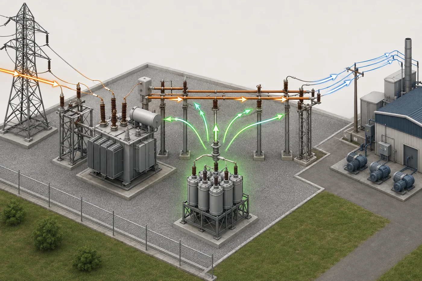
A feeder capacitor bank is connected in shunt to a distribution feeder and supplies reactive power near the part of the circuit that needs it. That local supply can reduce reactive current carried through the upstream conductor and transformer, improve voltage along the feeder, reduce part of the current-related loss, and release thermal capacity. It does not create real energy or correct every voltage problem. The result depends on load pattern, conductor impedance, system strength, regulator and tap settings, bank size, and when the bank is switched.
Substation Bus or Feeder Placement
A bank on the substation bus supports several outgoing circuits at one point and is simpler to coordinate as a central resource. A bank placed farther along one feeder can reduce reactive current over a larger length of that specific circuit and improve voltage closer to remote loads. The tradeoff is more field equipment, communication, protection, inspection, and switching coordination. A long rural feeder with seasonal motors may benefit from distributed steps, while a compact network with similar feeder profiles may favor a bus bank. Engineers compare alternatives with load-flow cases, not a fixed distance rule.
Fixed, Switched, and Controlled Banks
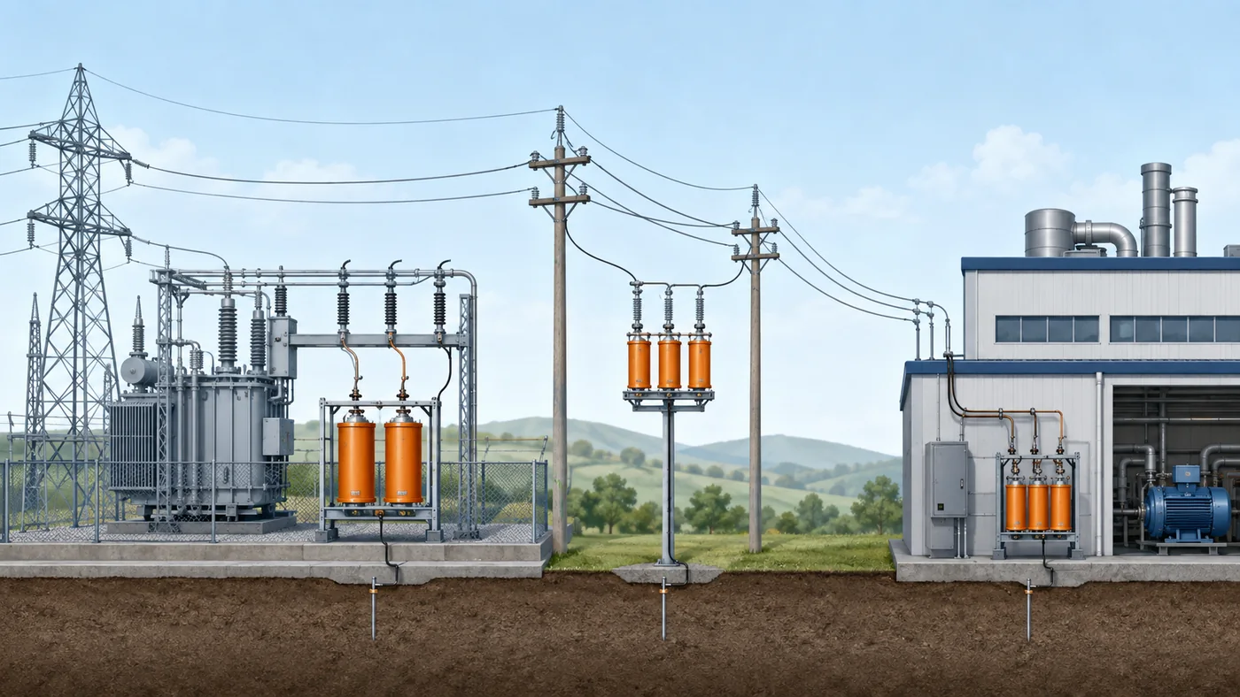
A fixed bank is appropriate only for reactive demand that remains present across the operating range. A switched bank follows predictable load changes using time, voltage, current, kvar, temperature, or supervisory commands. Control must avoid hunting when voltage regulators, transformer tap changers, distributed generation, and other banks respond to the same event. A controller deadband and delay should reflect feeder behavior rather than copied defaults. Remote indication is valuable because a failed switch, fuse operation, or unavailable bank can otherwise remain hidden until voltage or loss performance changes.
Use Load Profiles Before Choosing kVAR
Planning begins with time-aligned real power, reactive power, voltage, current, regulator operations, and power-factor data at the substation and relevant feeder points. Minimum-load conditions matter as much as peak load: a bank sized only for the evening peak may cause excessive voltage or leading vars when demand falls or solar export rises. Study representative seasonal and contingency cases. Separate normal voltage drop from problems caused by an overloaded transformer, poor connection, phase imbalance, conductor limitation, or a fault. A capacitor bank is justified only when reactive support addresses the actual constraint.
Estimate the Effect, Then Run the Study
A preliminary kvar estimate can show whether an option is plausible, but final placement needs a feeder model. The model should include source strength, transformer impedance and tap control, conductor sections, phase loading, existing regulators and capacitors, major motors, inverter-based generation, and expected switching states. Compare voltage at every relevant node, feeder current, losses, equipment loading, reactive exchange at the substation, and the largest voltage step. Unbalanced feeders may require phase-specific analysis. Document assumptions so future engineers can understand why the selected point and step size were accepted.
Coordinate Voltage Regulators and DER
A feeder bank changes the voltage observed by line regulators and load-tap changers. Poorly coordinated controls can produce unnecessary tap operations or alternating responses. Distributed solar and storage can reverse real-power flow while reactive demand follows a different pattern, so traditional time schedules may no longer match the feeder. Review sensing location, control direction, bandwidth, delay, seasonal settings, and supervisory priorities. Confirm behavior for loss of communications. The objective is a stable control hierarchy in which each device has a defined role, not several independent controllers chasing the same voltage.
Switching and Power-Quality Checks
Energizing a capacitor bank produces a transient. Back-to-back switching can be more severe when another bank is already energized nearby. Evaluate switch capability, restrike risk, inrush, surge protection, discharge time, and the voltage step seen by customers. Harmonic studies are required where drives, rectifiers, arc equipment, or inverter-rich loads could interact with feeder inductance and the bank. A fuse or point-on-wave controller does not replace a resonance assessment. Detuned reactors or other reactive-power technologies may be appropriate when a plain bank would create unacceptable duty.
Protection, Communications, and Maintenance
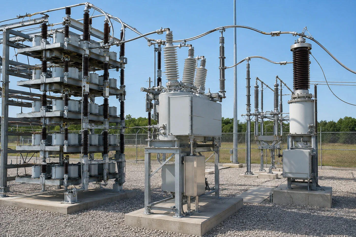
The design must coordinate bank fuses, phase and ground protection, unbalance detection, switching-device control, and upstream feeder protection. Provide visible position, alarm, and unavailable status where operationally useful. Maintenance planning should cover bushings, connections, fuse indicators, wildlife protection, corrosion, enclosure condition, switching operations, capacitance or current balance, and discharge/grounding procedure. Field crews need a drawing that matches the installed series and parallel arrangement. Any failed unit changes the bank condition and should be evaluated against permitted operation limits.
Check Each Operating Scenario
At minimum, compare peak load, normal daytime load, minimum overnight load, major-motor starting, feeder transfer, regulator out of service, one bank unavailable, and credible distributed-generation output. A solution that looks attractive in one snapshot may create a high-voltage condition or unnecessary switching in another. Review steady-state results and the step change when the bank enters or leaves service. Where customer processes are sensitive, evaluate the transient and voltage-change criteria used by the serving utility. Record the limiting case, because that case—not the average day—usually determines the acceptable bank step.
Measure Results After Energization
Commissioning should verify phase currents, bus and downstream voltage, kvar change, power factor, regulator or tap response, switching time, indication, alarms, and unbalance baseline. Compare measured values with the study and investigate material differences before accepting the installation. After several weeks, review operating counts and time-series data to find hunting, unnecessary overnight operation, failed commands, or a seasonal schedule mismatch. A placement project is successful when actual feeder voltage and reactive flow improve without creating new power-quality or maintenance problems. Continuous evidence also supports later decisions to retune, relocate, add, or remove steps.
A Practical Placement Comparison
No placement wins every study. Substation bus placement concentrates maintenance and provides broad voltage support. Feeder-head placement targets one circuit without sending the bank deep into the field. Mid-feeder placement can reduce reactive current across more conductor and support remote voltage, but it raises installation and operating complexity. Near-load placement is most selective and can avoid carrying reactive current over nearly the entire feeder, yet it depends on site access and load persistence. Use lifecycle cost, reliability, switching count, losses, voltage, and maintainability together.
| Местоположение | Main benefit | Main limitation | Best evidence |
|---|---|---|---|
| Substation bus | Central support for several feeders | Does not remove vars from individual feeder sections | Bus voltage and total reactive profile |
| Feeder head | Targets one circuit | Limited downstream loss relief | Feeder-head kvar and voltage cases |
| Mid-feeder | Remote voltage and conductor-current relief | More field equipment and coordination | Node voltage and seasonal load flow |
| Near load | Most local compensation | Load persistence and site access | Load-specific interval measurements |
RFQ and Design Review Checklist
State system voltage and frequency, feeder peak and minimum load, measured kvar profile, target voltage range, source short-circuit strength, transformer and regulator data, existing banks, distributed generation, proposed connection point, bank kvar and number of steps, switching frequency, communication method, fault current, insulation and environmental requirements, harmonic spectrum, protection philosophy, and applicable utility standards. Ask bidders to identify switching and fuse duties, discharge provisions, enclosure or rack arrangement, control fail-safe behavior, and required studies. CNBYG low-voltage compensation equipment fits plant-side projects; utility medium-voltage feeder banks require the correct voltage-class supplier and utility engineering scope.
Decision Record
Keep the approved study case, settings, drawings, commissioning measurements, and ownership of future setting changes together. This prevents later operating changes from defeating the original coordination and gives maintenance teams a clear basis for responding to an unavailable bank.
Related Guides
Start with why substations use capacitor banks, then review point-on-wave switching, capacitor-bank fusing, and the plant-side reactive-power product hub.
Часто задаваемые вопросы
Где следует устанавливать батарею конденсаторов фидера?
На шине, головном участке фидера, в середине фидера или вблизи нагрузки, в зависимости от результатов расчета установившегося режима, уровня напряжения, потерь, надежности и технического обслуживания.
Всегда ли установка фидера посередине более эффективна?
Нет. Он может снизить ток в вышестоящей цепи за счет большего количества проводников, но напряжение при легкой нагрузке, коммутация, доступ и управление могут перевесить это преимущество.
Можно ли использовать стационарный банк?
Только тогда, когда минимальная потребность в реактивной мощности может поглотить ее без недопустимо емкостного характера мощности или повышения напряжения.
Заменяет ли конденсаторная батарея регулятор напряжения?
Нет. Конденсаторы изменяют реактивную мощность и напряжение; регуляторы меняют положения ответвлений. Их управление должно быть скоординировано.
Может ли солнечная батарея изменить расположение конденсатора?
Да. Обратный поток активной мощности и дневное повышение напряжения могут изменить оптимальный размер, режим работы и метод управления.
Ссылки
- IEEE 1036 — Применение шунтирующих силовых конденсаторов
- Министерство энергетики США — Снижение затрат на реактивную мощность