


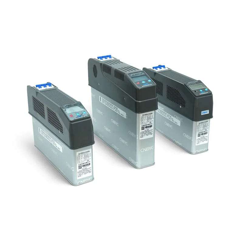
The choice between an intelligent capacitor and a conventional capacitor bank is mainly a system-architecture decision. An intelligent unit integrates some combination of measurement, control, switching, protection, indication, and communication with capacitor stages, reducing panel assembly and simplifying modular expansion. A conventional bank separates capacitors, controller, switching devices, protection, and optional reactors, giving designers more freedom to select and replace each component. Neither approach is automatically better. Compare load variability, harmonic conditions, available fault level, required kvar steps, service skills, spare-parts policy, communications, enclosure limits, and lifecycle maintenance. The final design must follow a site study and the actual product documentation rather than a generic feature checklist.
- Define the two architectures
- Where integration helps
- Where a conventional bank remains attractive
- Compare behavior under changing load
- Treat harmonics as a separate design input
- Maintenance and replacement strategy
- Specify communications and records
- A practical decision process
- Acceptance questions for both suppliers
- Validate the chosen architecture at site
- Таблица решений
- Источники и дополнительная литература
- Часто задаваемые вопросы
Define the two architectures
A conventional automatic capacitor bank is assembled from discrete functional blocks: controller, current measurement, fuses or breakers, contactors or electronic switches, discharge devices, capacitors, and—where the study calls for them—series reactors. An intelligent capacitor package combines several of those functions into a coordinated module. Product boundaries vary, so the word intelligent is not a complete specification. Ask which functions are genuinely included, what remains external, and how each protection function is coordinated. The comparison should be made between complete systems that deliver the same reactive-power objective at the same bus, not between one module and an unfinished conventional bill of materials.
Where integration helps


Integration can reduce internal wiring, panel footprint, component-matching work, and commissioning steps. Modular stages may be easier to add when the load grows within the system's design limits. Built-in displays or communications can expose stage status, temperature, alarms, and operating history. These benefits matter in distributed correction, compact electrical rooms, standardized panel production, and sites that value replaceable modules. They do not remove the need for upstream protection, conductor sizing, ventilation, earthing, short-circuit assessment, and a valid power-quality study.
Where a conventional bank remains attractive
Discrete banks provide freedom to choose capacitor duty, reactor tuning, switching technology, controller logic, protection, enclosure form, and stage sizes independently. That flexibility is valuable for large ratings, unusual voltages, high fault levels, special harmonic conditions, or owner standards that require approved component families. Individual parts can often be tested and replaced without changing the rest of the architecture. The tradeoff is more engineering coordination, wiring, assembly, test effort, and spare-part variety. A conventional bank is not inherently less intelligent; it can include advanced control and monitoring while retaining discrete power components.
Compare behavior under changing load
The smallest effective step and switching response determine how closely either solution follows demand. A compact intelligent module may offer convenient modular stages, while a conventional panel can be designed with unequal or binary step ratios. Evaluate the load profile rather than counting stages. Fast cyclic loads can cause excessive mechanical switching if delays and step sizes are poorly chosen. Very rapid compensation needs may point to static var generation or a hybrid architecture, not simply a faster capacitor switch. The U.S. Department of Energy notes that fixed capacitors suit steady loads while switched correction is appropriate when loading varies; that principle applies regardless of packaging.
Таблица решений
| Decision factor | Intelligent capacitor architecture | Conventional capacitor bank | Evidence to request |
|---|---|---|---|
| Integration | More functions packaged in a coordinated module | Functions selected and wired as discrete components | Functional block diagram and scope boundary |
| Design flexibility | Usually within a defined modular platform | High freedom for stages, reactors, switches and protection | Approved drawings and component data |
| Expansion | Potentially simple within module and bus limits | Possible but may require panel and protection changes | Maximum modules, bus rating and study limits |
| Обслуживание | Module diagnostics and replacement can be straightforward | Individual components can be tested and replaced | Isolation method, spares list and service procedure |
| Harmonic application | Depends on documented integrated design and limits | Reactor and capacitor combination can be engineered explicitly | Harmonic study and permitted operating envelope |
Treat harmonics as a separate design input

Capacitors interact with system inductance and can shift or amplify resonance. An anti-harmonic label should be translated into actual construction, reactor arrangement, permitted harmonic environment, and application limits. Review measured voltage and current spectra, transformer impedance, existing capacitors, nonlinear loads, and the point of common coupling. A conventional detuned bank offers explicit reactor selection; an integrated unit may include a coordinated reactor or may have defined limits that require another mitigation method. Neither architecture should be applied from power factor alone when harmonic distortion is material.
Maintenance and replacement strategy
Ask how a technician isolates one stage, verifies discharge, tests capacitance, checks switching operation, retrieves alarms, and returns the system to service. Intelligent modules can simplify swap-out but may tie replacement to a particular platform or communication protocol. Conventional banks may use broadly available components but require more diagnosis and correct matching. Compare expected spare holdings, vendor support, firmware dependence, parameter backup, and the consequences of one module failing. A lifecycle decision includes outage duration and diagnostic skill, not just purchase price.
Specify communications and records
For integrated monitoring, define protocol, data points, address management, timestamps, alarm retention, cybersecurity boundary, and ownership of configuration files. Confirm that local operation remains understandable if the supervisory system is unavailable. For a conventional bank, decide whether the controller alone supplies status or whether individual stage feedback and temperature monitoring are required. In both cases, record actual connected stages, switching counts if available, kvar response, voltage, current, power factor, and harmonic conditions during acceptance testing.
A practical decision process
First define the reactive-power requirement and operating envelope. Second, rule out unsafe capacitor application through harmonic and short-circuit review. Third, compare complete architectures using the same acceptance criteria: kvar range, smallest step, voltage, fault duty, environmental limits, protection, switching life, communications, service method, and expansion. Fourth, request drawings, component data, manuals, test records, and a clear responsibility matrix. Finally, validate the selected system under representative loads. This process turns a marketing comparison into an engineering decision.
Acceptance questions for both suppliers
Ask both suppliers to return the same schedule rather than unrelated brochures. Require the delivered kvar at actual voltage, step arrangement, maximum current, fault-duty boundary, protection scope, harmonic limits, enclosure heat loss, communication points, spare-parts recommendation, isolation method, and acceptance tests. Identify whether a failed module or component can be isolated while the remaining stages operate. Confirm how settings are backed up and how replacement hardware is matched to the installed revision. A side-by-side response exposes missing scope and prevents a lower quoted price from hiding external controller, switching, reactor, protection, or commissioning costs.
Validate the chosen architecture at site
Commission the system against a common acceptance sheet. Record bus voltage, active and reactive power, power factor, connected stages, stage current balance, temperature, alarms, and harmonic conditions at light and representative production loads. Command or observe every available stage and verify that its physical response matches the indicated status. Test loss of communications without disturbing local control, and prove that configuration backups can be restored using the approved procedure. Inspect discharge behavior and minimum reconnection time before repeated switching. For a conventional bank, confirm each discrete component matches the approved bill of materials. For intelligent modules, confirm addresses, firmware or hardware revisions, and module-sharing logic. The comparison is complete only when the selected architecture delivers stable correction and maintainable records under the site's actual operating states.
How this topic connects to CNBYG equipment
This guide supports specification and commissioning discussions for the Intelligent capacitor product line. Product data must be checked against the actual system voltage, load profile, harmonic measurements, protection design, environmental conditions, and applicable project requirements. Share a single-line diagram and representative measurements before requesting a model recommendation.
Related CNBYG engineering guides
- how an intelligent reactive power capacitor works
- what capacitor banks are and how they operate
- compare SVG and ASVG for dynamic compensation
Источники и дополнительная литература
Земля U.S. Department of Energy motor-driven systems guide explains where fixed and automatically switched power-factor correction can fit industrial load patterns. OSHA 1910.333 provides the U.S. baseline for de-energizing and electrical work practices. IEEE 519 is the standards-body reference for harmonic control at the point of common coupling. Apply the current editions and local requirements for the project.

Further learning: MIT OpenCourseWare Lecture 4: Power Factor. The MIT lecture explains power factor and distortion; it does not replace project-specific equipment instructions.
Часто задаваемые вопросы
Is an intelligent capacitor the same as a complete APFC panel?
Not always. The included measurement, switching, protection and communication functions vary by product. Confirm the complete scope and required external components.
Does an intelligent capacitor eliminate harmonic resonance?
No generic product label can guarantee that. Harmonic measurements and network impedance must be reviewed for the actual installation.
Which option is easier to maintain?
Integrated modules may simplify replacement, while conventional banks allow individual-component repair. The better choice depends on spares, skills, documentation and outage needs.
Can either option be expanded later?
Possibly, but expansion must remain within bus, protection, enclosure, thermal, fault-duty and harmonic-study limits.
Final engineering note: Treat formulas and checklists as screening tools. Installation, protection, commissioning, and energized testing must be performed by qualified personnel using approved drawings, product manuals, studies, and site safety procedures.