Коммутация конденсаторных батарей в заданную точку волны напряжения
point on wave switching for capacitor banks closes each capacitor step when the AC bus voltage matches the voltage on the capacitor terminals so the instantaneous voltage difference—and the inrush current spike—stays small. Automatic power-factor cabinets use that synchronized timing so stages can switch without the fuse trips, contact wear, and bus disturbances that random contactor closure often creates.
This guide explains the inrush mechanism, zero voltage switching capacitors use when a bank is discharged, residual capacitor voltage after switch-off, back-to-back switching hazards on one bus, and how contactors compare with compound switches and integrated intelligent modules in a synchronized switching capacitor bank cabinet. For what a bank is and how it fits plant reactive-power correction, start with our separate article on what are capacitor banks; this page does not repeat that definition or any power-factor calculation walkthrough.
What Point-on-Wave Switching Means for Capacitor Banks
Point-on-wave switching—often called synchronized switching or controlled switching—means the controller closes the switch at a calculated instant on the AC waveform so the voltage across the opening contacts is as small as practicable.
Capacitors oppose sudden voltage change. If the bus is already at high instantaneous voltage while the capacitor terminals are still near zero, the closing event applies nearly the full difference at once. PoW logic measures the live wave, predicts where voltage will be when the mechanical or hybrid switch actually finishes closing, and fires the command early enough to land on the target angle.
On a fully discharged bank the usual target is a zero-voltage close. On a bank that was opened moments ago the target may be peak voltage or an intermediate level while charge bleeds off through discharge resistors or while the controller tracks residual state.
Utility transmission engineers apply the same idea on high-voltage breakers with dedicated controlled-switching devices. Low-voltage automatic PF cabinets apply it through compound switches, thyristor-assisted relays, or integrated intelligent capacitor modules. The physics is shared even when the hardware size differs.
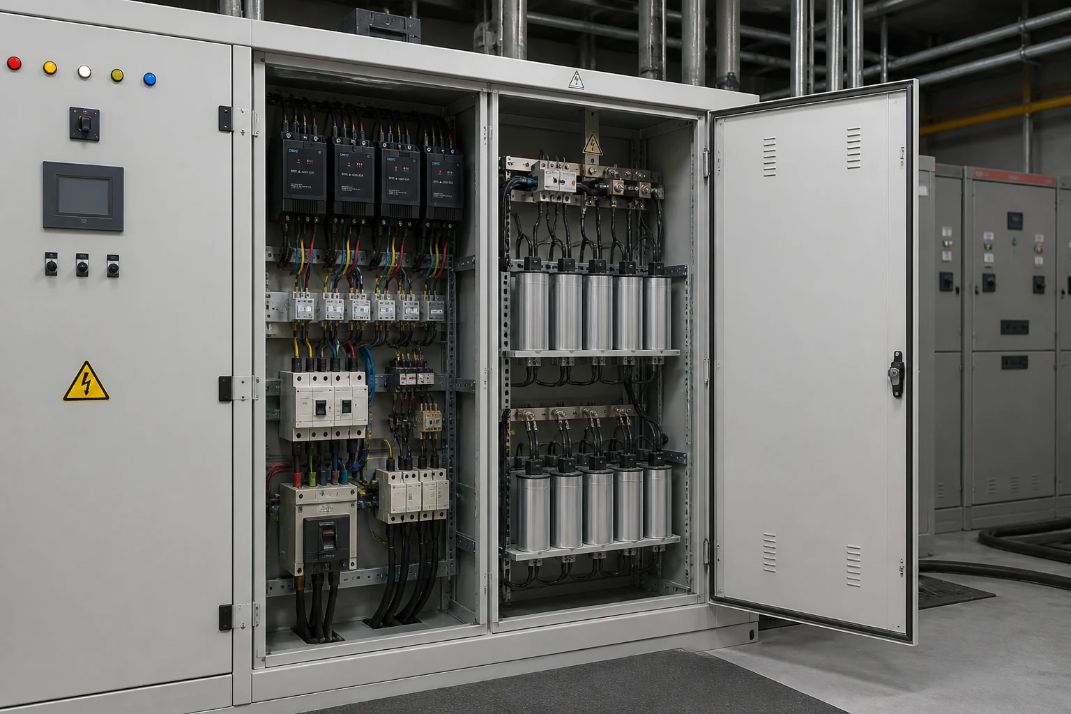
Why Capacitor Bank Switching Creates Inrush Without Control
Capacitor bank inrush current appears because charging current must flow whenever terminal voltage is forced to change faster than the capacitor can follow.
In AC terms the relationship is familiar: current is proportional to how quickly voltage changes across the capacitance. A random contactor closure can therefore produce a wide spread of peak currents for the same kvar step depending on where the sine wave was when the contacts touched.
Several plant factors widen that spread:
- System impedance — a stiff bus with low source impedance allows larger transient peaks.
- Pre-switch charge — a capacitor that still holds voltage from a recent open sees a different ΔV than a discharged unit.
- Parallel paths — another energized bank on the same bus changes the effective LC network.
Uncontrolled switching is not always catastrophic on a single small fixed step that rarely opens. It becomes painful in automatic cabinets where a controller may add or remove multiple steps per hour chasing a varying motor load.
Подсказка: Opening a step at current zero leaves the capacitors charged. A controller that tries to re-close too quickly without tracking that trapped residual capacitor voltage is still doing “random” switching even if marketing copy mentions zero-cross. — source: utility controlled-switching guides for capacitive loads (research extract on residual charge targets)
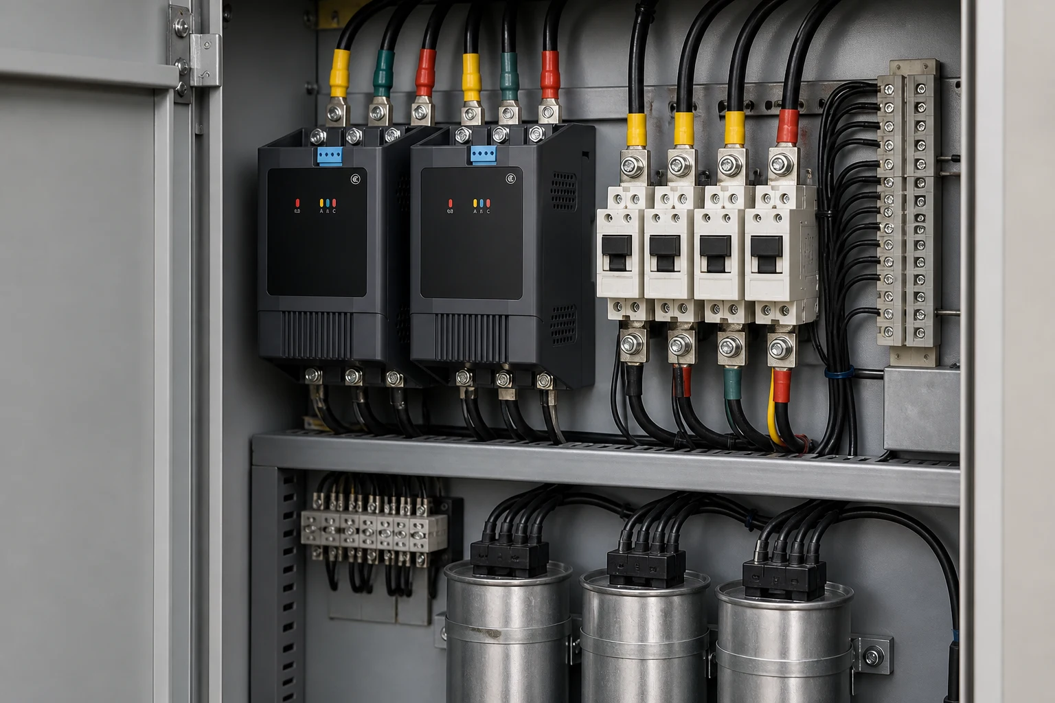
Zero-Voltage Closing and Residual Charge After Switch-Off
Zero-voltage switching for capacitors is the special case where the bank is fully discharged and the controller targets a close at—or very near—the system voltage zero-crossing.
At that instant both the bus and the capacitor terminals sit near zero, so the first current builds as the sine wave rises naturally rather than as a step. That is the ideal most LV compound switches and intelligent capacitor modules advertise.
Reality adds two complications procurement readers should expect:
- Mechanical and hybrid delay — the close command must lead the target by the switch’s operating time. Controllers therefore continuously measure the wave and compensate for scatter.
- Residual capacitor voltage after open — when current goes to zero the capacitors remain charged near line peak until discharge resistors or time decay reduces it. Re-closing while charge remains means the target angle is no longer a zero-voltage close. Advanced PoW systems track whether the bank is discharged, fully charged, or somewhere between—as described in utility controlled-switching guides for capacitive loads.
| Capacitor charge state when close is requested | Typical PoW close target | Reader takeaway |
|---|---|---|
| Fully discharged | Voltage zero-cross | Minimizes initial ΔV |
| Fully charged (just opened) | Voltage peak | Matches trapped charge |
| Partially discharged | Intermediate angle on the wave | Controller must track decay, not assume zero volts |
Without that state awareness, a cabinet may still slam steps at the wrong angle while the HMI label says “zero-cross.”
Back-to-Back Energization on the Same Bus
Back-to-back switching and back-to-back energization both describe closing a capacitor step while another bank or step is already connected on the same bus. The second closure can produce very high inrush even when each step’s nameplate kvar looks modest.
The already-energized capacitors present a low-impedance path. The incoming step sees a stiff voltage source combined with the first bank’s stored energy, which can drive transient currents far above steady-state reactive current. Educational overviews of capacitor switching describe inrush frequencies from hundreds of hertz to a few kilohertz in severe same-bus cases.
Plant scenarios where this shows up:
- A controller adds step 3 while step 2 is still online instead of swapping steps.
- Two independent automatic cabinets share one compensation bus without interlocking.
- Rapid cycling after a brief outage when multiple stages try to return together.
PoW on each individual step helps but does not replace coordination logic. Minimum time between operations, interlocks, and controller algorithms that avoid overlapping closes still matter. CNBYG’s published BYFK composite-switch specification table, for example, lists minimum intervals between turn-on/turn-off and between consecutive connections—parameters buyers should align with controller programming, not ignore.
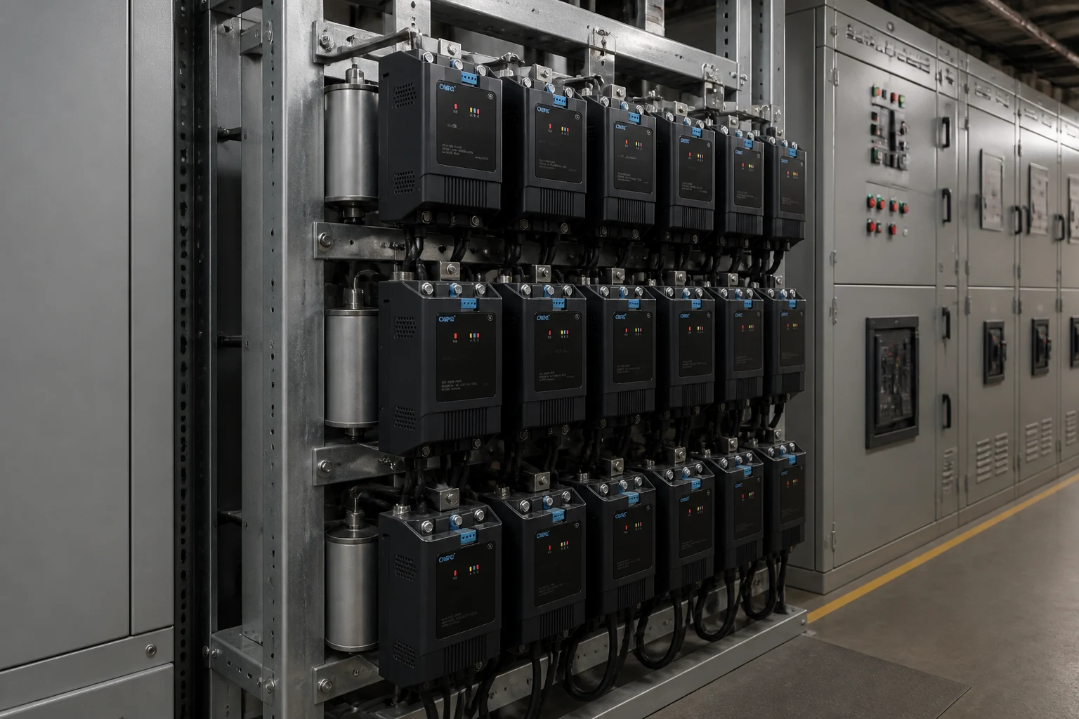
Contactor, Compound Switch, and Breaker-Based Point-on-Wave Control
Three hardware classes cover most conversations—from LV cabinets to utility substations.
| Approach | How PoW is implemented | Typical fit | Watch-out |
|---|---|---|---|
| Capacitor switching contactor (e.g., dedicated CJ19/GJ19 class) | Often basic timing; may rely on controller pre-contact or auxiliary logic | Cost-sensitive fixed steps with infrequent switching | Random-angle closes still possible if controller does not synchronize |
| Compound / composite switch (semiconductor + magnetic hold relay) | Microprocessor selects turn-on at voltage zero and turn-off at current zero | LV automatic PF cabinets with frequent stepping | Still needs correct residual-voltage logic and minimum intervals |
| HV breaker + controlled switching device (CSD) | Breaker with high repeatability; rate of decrease of dielectric strength (RDDS) and pole-scatter budgets per IEEE application guides | Utility and large MV banks | Not a direct substitute for LV compound-switch specs |
High-voltage application notes stress breaker repeatability on the order of ±0.5 to ±1.0 ms and sufficient rate of decrease of dielectric strength (RDDS) when zero-cross is the target. Those numbers belong to breaker selection on transmission systems, but they explain why “any contactor with a zero-cross label” is not interchangeable with a compound switch engineered for capacitive duty.
At low voltage, the reactive power compensator hub groups controllers, switches, and capacitor steps that are specified together. Switching hardware should be chosen with the controller’s PoW algorithm, not as an orphan part number.
When Point-on-Wave Switching Pays Off in LV Plant Cabinets
Point-on-wave switching pays off most when capacitor steps switch often and when inrush would otherwise limit how aggressively the controller can follow load.
Strong fits:
- Multi-step automatic PF cabinets on motor-heavy plants where lagging reactive demand swings across shifts.
- Steps large enough to disturb the bus when closed at a bad angle—nuisance fuse operations, contact pitting, or voltage flicker on sensitive loads.
- Projects where the utility or internal power-quality spec limits switching transients even if steady-state power factor already looks acceptable.
Weaker fits:
- A single fixed capacitor step that rarely disconnects—PoW hardware adds cost with little operational benefit.
- Plants where гармонические искажения, not switching angle, is the primary failure mode—see the limit below.
Published extra-high-voltage studies comparing uncontrolled energization with point-on-wave zero-cross control report large reductions in peak transient current and voltage in their test and simulation cases. Those figures illustrate the mechanism; they are not LV nameplate guarantees for your site.
Automatic stepped banks also multiply exposure: each energization is another transient event. Educational material on shunt capacitor applications notes that switching overvoltages and inrush accompany automatic banks even when steady-state power factor improves.
Важно: Point-on-wave switching limits energization stress; it does not detune a bank against harmonic resonance. Field discussions of automatic PF stages describe humming reactors, overheated capacitors, and blown fuses when plain capacitors interact with nonlinear loads—symptoms that PoW alone will not cure. Detuned reactors, harmonic analysis, or active solutions may still be required on distorted buses. — source: IPQDF harmonics and power factor capacitors
Choose Switching Hardware and BYFK Product Fit for Capacitor Bank Steps
When you specify hardware for a new or retrofitted cabinet, match the switch class to how often stages move and how much inrush your bus can tolerate.
Conventional capacitor contactors such as the GJ19 series switching capacitor contactor remain appropriate where steps are few, switching is slow, and the controller’s strategy is conservative. They are the baseline comparison in many bids—not the end of the story for aggressive automatic controllers.
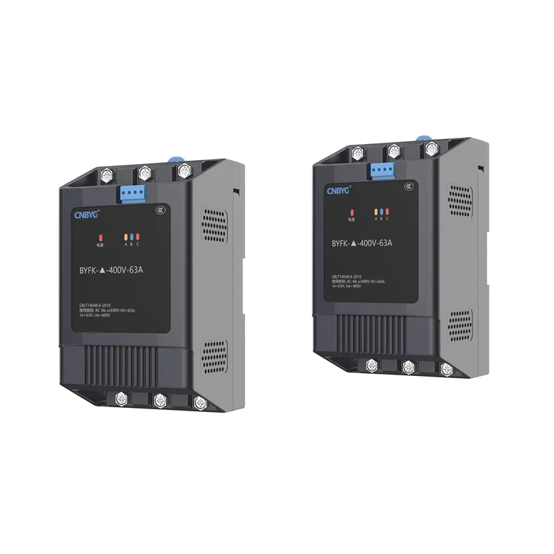
Compound switches such as the BYFK series intelligent low-voltage composite switch target capacitive duty with voltage zero-crossing conduction and current zero-cross cutoff. CNBYG’s published specification table for BYFK lists inrush below 1.5 times rated current, response time under one second, minimum five-second spacing between turn-on and turn-off, and thirty-five seconds between consecutive connections—values that should be checked against your controller’s staging profile.
Integrated intelligent capacitors such as the BY81 series intelligent capacitors embed measurement, control, and synchronous zero-crossing switching inside the module when a distributed step-by-step architecture fits better than a central contactor bank.
Whichever path you take, confirm three items with the supplier and your panel builder:
- Controller and switch share one PoW algorithm including residual-voltage handling.
- Minimum intervals and interlocks prevent back-to-back overlaps your bus cannot absorb.
- Harmonic study precedes energization on VFD-heavy plants—PoW is not a substitute for detuning.
Часто задаваемые вопросы
What is point on wave switching for capacitor banks?
It is controlled closing (and sometimes opening) synchronized to a target angle on the AC voltage wave so the voltage difference across the switch at contact make is minimized, which limits inrush when the step connects.
Why does switching a capacitor bank cause inrush current?
Capacitors require current whenever terminal voltage changes quickly. Closing at a high instantaneous ΔV forces a large charging current until the capacitor matches the bus.
Is zero voltage switching the same as point on wave?
Zero-voltage switching is the discharged-bank case of point-on-wave control—closing at or near zero volts. PoW also covers closes at peak or intermediate angles when residual charge remains after a previous open.
What is back-to-back capacitor bank switching?
It is energizing a second bank or step while another is already connected on the same bus. The combined network can produce much higher transient current than either step alone.
Does switching off discharge the capacitors immediately?
No. When current is interrupted at zero, capacitors typically retain near-line voltage until discharge resistors or time decay reduces it. The next close must account for that trapped charge.
Do I still need detuning if I use point on wave switching?
Often yes on plants with significant harmonics. PoW reduces energization transients; it does not move resonance points away from characteristic harmonics the way a detuned reactor bank does.
Can low-voltage plants use point on wave switching?
Yes. LV automatic PF cabinets commonly use compound switches or integrated intelligent capacitors with zero-cross control rather than utility-scale breaker CSDs.
How is a compound switch different from a capacitor contactor?
A compound switch uses intelligent timing plus hybrid switching elements to target voltage zero-cross turn-on and current zero-cross turn-off for capacitive duty. A conventional contactor may rely on simpler mechanics unless paired with a controller that truly synchronizes every close.
Ссылки
- IEEE Technology Navigator — Capacitor Banks and controlled switching
- E3S Web of Conferences — Diminution of Transient Disturbances for High Voltage Application Integration
- IEEE SA — IEEE C37.012-2022 Guide for Application of Capacitive Current Switching
- Electrical Technology — Capacitor Banks Characteristics and Applications
- IPQDF — Harmonics and Power Factor Capacitors: Understanding Failure, Resonance, and the Filter Solution