



Коррекция коэффициента мощности для индукционных двигателей
Power factor correction for an induction motor should follow the motor’s real operating profile, starting method, speed control and measurement boundary. A motor that runs near full load may need steady reactive support, while the same motor at idle or during a stop can make a fixed capacitor excessive. The practical objective is a stable source-side power factor without damaging the motor, creating self-excitation, or forcing an SVG and a capacitor bank to fight each other.
Земля Страница продукта CNBYG SVG shows the product context for dynamic compensation. Select current, control priority and protection from measured motor data and the approved electrical design, not from the motor nameplate alone.
Start with the motor operating states
Record motor rating, voltage, frequency, efficiency class, starting method, duty cycle, speed-control equipment and the driven load. Capture stopped, unloaded running, normal production, overload and transition states where safe. A motor’s reactive demand is not constant: magnetizing current remains at light load and changes in speed, slip and voltage alter the reading.
Identify whether the correction point is at the motor terminals, the motor feeder, a common MCC bus or the plant incomer. A capacitor mounted at the motor can correct that motor, but it must be coordinated with a VFD, soft starter and switching device. An SVG at the MCC or incomer can serve multiple motors, but it needs a CT boundary that does not accidentally include or exclude the wrong feeders.


Диагностическая таблица решений
| Motor observation | Вероятная причина | Первая проверка |
|---|---|---|
| PF is low only when the motor is lightly loaded | Magnetizing current is a larger share of input current. | Trend PF against kW, speed and running state. |
| PF becomes leading after the motor stops | Motor capacitor remains connected or a common bank is oversized. | Interlock capacitor switching with the motor contactor. |
| PF falls during VFD operation | True PF, displacement PF and converter current are being mixed. | Confirm meter definition and measure at the correct boundary. |
| Starting current causes alarms | Capacitor or SVG response is not coordinated with starting. | Review start permissives, delay and protection settings. |
| PF differs between motor and MCC meters | CT ratio, phase, harmonics or boundary mismatch. | Compare synchronized traces with an independent analyzer. |
| Correction works at one speed only | Load torque and VFD operating point vary. | Build a speed/load profile before selecting capacity. |
Verify displacement and true power factor
A conventional motor with sinusoidal supply may be described mainly by displacement power factor, but a VFD changes the waveform and current spectrum. Confirm whether the utility or plant specification uses true PF including harmonics, displacement PF, or a specific demand calculation. Do not size a capacitor from a display that uses a different definition from the billing meter.
Check CT polarity, phase sequence, voltage reference, ratio and location. Compare the motor feeder, MCC and incomer readings during a controlled load change. The Руководство по компенсации реактивной токи SVG shows how a correct controller can appear ineffective when the CT boundary or sign convention is wrong.
Motor capacitor versus central SVG
Motor-mounted capacitors can reduce feeder current when the motor runs steadily and the capacitor is switched with the motor. They must be selected with the motor manufacturer or electrical designer because excessive capacitance can produce self-excitation during coast-down, switching transients or a disconnected supply.
Central APFC or SVG equipment is more flexible when many motors have changing duty cycles. An SVG can respond continuously and can also reserve current for harmonic or unbalance compensation, but its available kvar depends on voltage and total current. The Руководство по напряжению сети и мощности SVG explains why low voltage may reduce the practical kvar output.
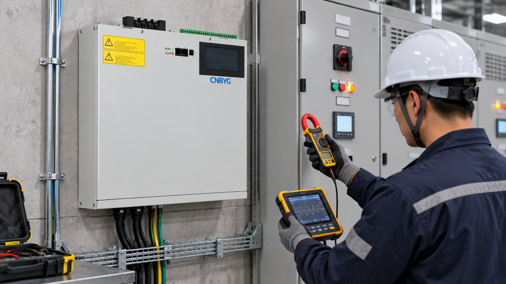
Use the simplest architecture that matches the duty. A stable, dedicated motor with a known operating point may suit a switched local capacitor. A variable-speed pump line, compressor train or mixed MCC often benefits from central dynamic control. In both cases, keep the correction device out of the motor-starting circuit unless the design explicitly validates the sequence.
A practical calculation method
Measure active power and PF at the chosen boundary at normal load. If the specification uses displacement PF, calculate the required reactive change with the same convention. A common relationship is:
[
Q_c = P\left(\tan(\cos^{-1}PF_1)-\tan(\cos^{-1}PF_2)\right)
]
Use consistent units and treat the result as a starting estimate. Validate it against the motor’s actual kW, voltage and speed. For a three-phase system, check current using (I_Q=Q/(\sqrt{3}V_{LL})), especially at the lowest expected voltage. If the SVG also performs harmonic filtering, reserve current for that function.
Do not calculate from the motor’s kW rating if it normally operates at half load. Record at least three representative points and choose a target band that avoids leading PF at minimum load. Add only a documented margin for motor variation, not an arbitrary oversized bank.
Coordinate starts, stops and variable speed
Create a switching sequence for contactor, soft starter, VFD, capacitor and SVG. The capacitor should not remain connected to a motor that has stopped unless the design specifically allows it. A VFD output must not be connected to a conventional power-factor capacitor unless the VFD manufacturer and designer approve the arrangement; correction is normally applied on the line side with suitable protection.
For a soft starter, define when the bypass closes and when correction is permitted. For a VFD, log speed, torque proxy, input current, DC-link behavior where available and the meter’s PF definition. For multiple motors, a central controller should know which feeders are online or use a stable measurement boundary that includes the combined load.
Земля Руководство по установке SVG covers clearances, cable entry and cooling. The Список задач по настройке SVG can be used to record phase sequence, CT checks, interlocks and as-left settings.
Commissioning and acceptance
Test the motor stopped, running unloaded, at normal production and at the highest permitted load. Include a start and stop sequence under an approved procedure. Record kW, kvar, voltage, current, PF definition, speed, capacitor state, SVG current, THD, alarms and protection status. Verify no leading condition appears during a stop or a rapid load drop.
Where a generator or UPS can supply the motor, test transfer only with an approved switching plan. Generator voltage regulation, minimum loading and fault-current limitations may change the safe correction range. For measurement methods, use the Вставка из каталога IEC 61000-4-30 в качестве отправной точки и следуйте спецификациям проекта.
Compare the final result with the source meter and the motor feeder meter. If they disagree, keep the discrepancy open until CT boundary, phase and PF definition are reconciled. Do not declare success from a single motor display.
Общие ошибки, которых следует избегать
The most common error is selecting a capacitor from the motor nameplate PF and assuming the motor always runs at rated load. Another is leaving a motor capacitor connected when the motor contactor opens. A third is applying the same correction logic to a VFD and a direct-on-line motor. A fourth is using an SVG target that ignores current reserved for harmonic filtering.
It is also risky to let a local APFC relay and a central SVG respond to the same motor feeder with similar delays. Choose a primary controller, define a deadband and document the fallback. A stable target band is normally more useful than an exact unity setting that causes hunting.
Record the motor duty envelope
Keep the motor identification, driven process, starts per hour, normal speed range and permitted stop sequence with the correction settings. Note whether the motor can regenerate during a coast-down and whether a bypass contactor changes the measurement boundary. If several motors share a bus, identify the combinations that can run together and repeat the PF check after a production schedule change.
Use one controlled change at a time. Save the before and after trend, capacitor state, SVG current and protection status. A clear rollback value helps the maintenance team restore a stable state if the process changes before a full retest is possible. Recheck the low-load case after any motor replacement, VFD parameter change or feeder relocation.
Часто задаваемые вопросы
Моторный конденсатор всегда является наилучшим методом коррекции?
Нет. При правильном включении и защите он может обеспечить стабильную работу двигателя. Применение системы с переменной скоростью вращения или смешанной системы MCC часто требует центрального динамического компенсатора.
Можно ли подключить конденсатор к выходу VFD?
Не в качестве стандартной практики. Следуйте рекомендациям производителя и проектному решению; исправление обычно выполняется на линии с соответствующей защитой.
Почему мотор PF теряет мощность при легком нагрузке?
При уменьшении полезной механической мощности остаётся постоянной магнитная сила тока, поэтому реактивная сила тока становится более существенной составляющей общего тока.
Что доказывает, что коррекция была скоординирована?
Документированные испытания на запуск/остановку, CT- и фазовые проверки, синхронизированные измерения источника и питающего устройства, состояние конденсатора/SVG, состояние защиты и отсутствие запуска при минимальной нагрузке.
Заключение
Power factor correction for induction motors starts with the motor’s real duty cycle and the correct measurement boundary. Select local capacitors or a central SVG only after checking starts, stops, speed control, voltage, current and coordination. Validate the result across unloaded, normal and peak operation so the improvement remains safe when production changes.
Neutral video: motor power-factor background
The NPTEL lecture below is neutral educational context on power factor and reactive power, not a product recommendation.
