


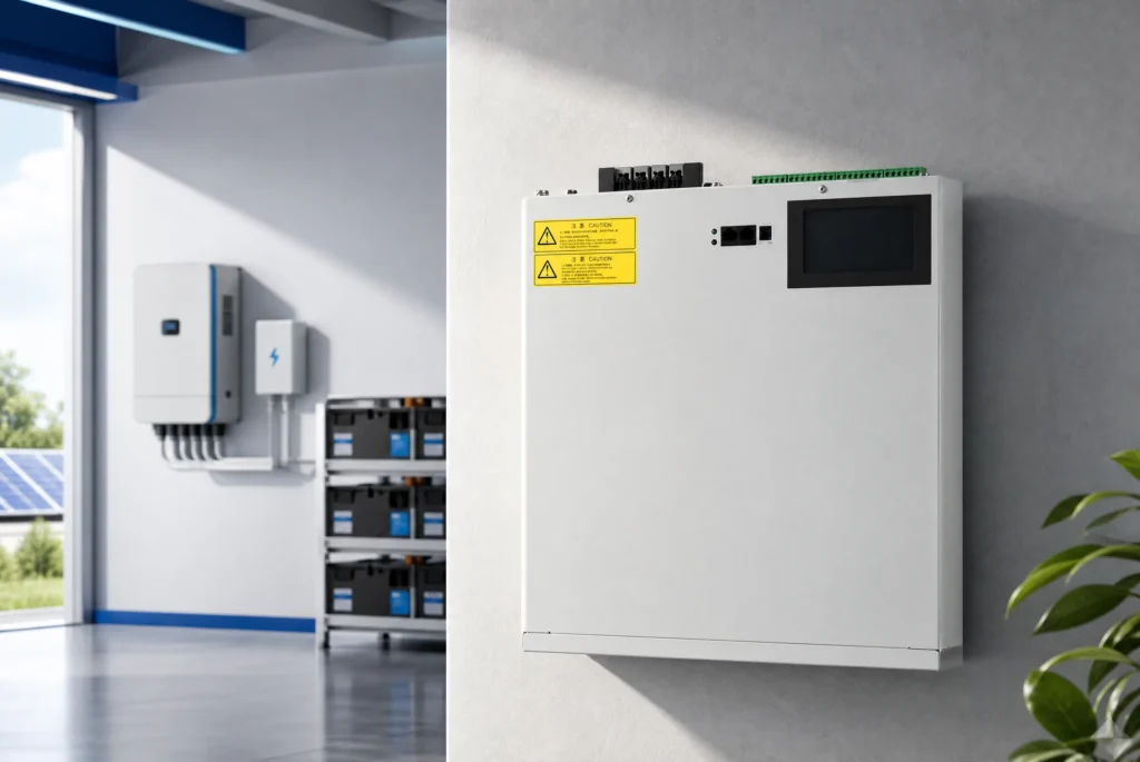
Static var compensator cooling removes losses from thyristor valves, reactors, capacitors, filters, transformers, and auxiliaries so the SVC can deliver its required reactive output without exceeding component temperatures. Small or enclosed systems may use forced air; high-power valve systems often use a closed deionized-liquid loop and external heat exchanger. The correct design is based on loss data at the hottest electrical operating point, site ambient and altitude, contamination, redundancy, building heat rejection, monitoring, and the output available after a fan, pump, or chiller failure.

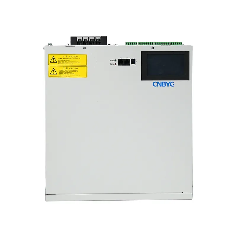
What SVC Cooling Must Remove
A static var compensator produces heat in thyristor valves, reactors, capacitors, filters, transformers, buswork, control power supplies, and enclosure auxiliaries. Losses vary with topology and operating point. A thyristor-controlled reactor can run for long periods at high current, while switched branches have a different duty cycle. Cooling is sized from component losses and the hottest credible operating state, not only from the SVC Mvar nameplate. The study also includes solar gain, ambient temperature, altitude, contamination, enclosure absorption, ventilation recirculation, and loss of one cooling component.
Air Cooling
Forced-air systems move filtered or conditioned air through cabinets, valve rooms, or heat sinks. They are comparatively simple, but performance depends on airflow, air density, filter condition, fan availability, and a clean path from inlet to outlet. Hot-air recirculation can make measured room temperature look acceptable while semiconductor heat sinks overheat. At altitude, reduced air density lowers cooling capability. Dust, salt, conductive particles, and humidity may require sealed heat exchangers or conditioned rooms rather than open ventilation. Fan redundancy and dirty-filter alarms should match the required availability.
Liquid Cooling
High-power thyristor valves often use a closed deionized-water or water-glycol circuit to move heat from valve heat sinks to an external heat exchanger. The primary circuit must maintain electrical insulation, chemistry, cleanliness, pressure, flow, and leak integrity. Pumps, expansion vessel, deionizer, filters, conductivity measurement, flow switches, temperature sensors, and heat exchangers become part of SVC availability. A secondary air or water circuit rejects heat to the site. Liquid cooling can handle concentrated losses efficiently, but it adds water-quality control, freeze protection, leak detection, and maintenance responsibilities.
Heat Exchangers and Redundancy
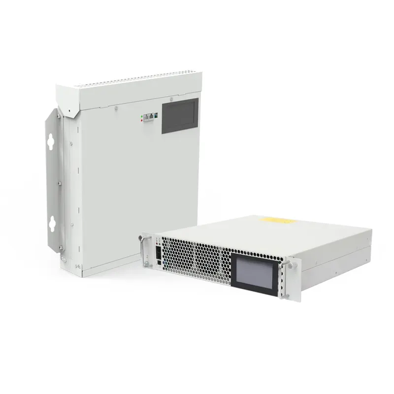
Define whether the heat is rejected by air-to-water radiators, water-to-water exchangers, chillers, cooling towers, or site process water. Check the true worst-case sink temperature, fouling allowance, approach temperature, and loss of a fan, pump, or exchanger section. N+1 language is incomplete unless the duty point is stated. One standby pump may not preserve full output if the remaining exchanger area or electrical supply is the limiting element. Specify the SVC output available in normal cooling, one-component-out operation, high ambient, and emergency derated conditions.
| Cooling method | Best fit | Key monitored condition | Main failure concern |
|---|---|---|---|
| Forced air | Moderate distributed losses | Airflow and filter pressure | Fouling and recirculation |
| Closed liquid loop | Concentrated valve losses | Flow, temperature, conductivity | Leak, pump, or chemistry failure |
| Chilled secondary loop | High ambient or tight room limits | Supply temperature and chiller state | Auxiliary dependence |
| Sealed heat exchanger | Dusty or corrosive sites | Internal temperature and exchanger condition | Reduced approach and fouling |
Ambient Temperature and Altitude
Equipment ratings normally assume a defined ambient and elevation. Higher ambient reduces temperature headroom; altitude reduces air density and can also affect insulation coordination. Use site meteorological design values, indoor room rise, solar radiation, and ventilation discharge location. Do not size to annual average weather when the grid needs reactive support during a rare hot peak. Consider cold starts, condensation, heater operation, and freeze protection as well. If the project applies derating, state whether it limits continuous Mvar, short-time overload, harmonic filter duty, or semiconductor current.
Contamination and Enclosure Strategy
Cement dust, coal dust, metal particles, textile fibers, salt fog, oil mist, and corrosive gases change the cooling decision. Open filtered air may require frequent maintenance and still allow deposits on heat sinks or insulation. A sealed cabinet with air-to-air or air-to-water heat exchange isolates internal air but adds thermal resistance. Positive pressure, filter class, gasket design, cable entry, drainage, and door discipline matter. Choose an enclosure concept from the actual contaminant and maintenance capability; a high IP number alone does not describe heat rejection, corrosion protection, or filter loading.
Temperature Sensors and Alarms
Measure where failure develops: semiconductor heat sink or junction estimate, valve cooling inlet and outlet, reactor winding or core where provided, capacitor compartment, cabinet inlet and exhaust, coolant conductivity, pressure, flow, pump status, fan status, filter differential pressure, room temperature, and leak detection. Use warning, derating, and trip levels with time delays appropriate to thermal inertia. A single room thermostat cannot prove valve cooling. Trends are more useful than isolated alarms because a slowly rising temperature at the same load can reveal fouling, pump wear, blocked airflow, or degraded heat transfer.

Control and Derating Logic
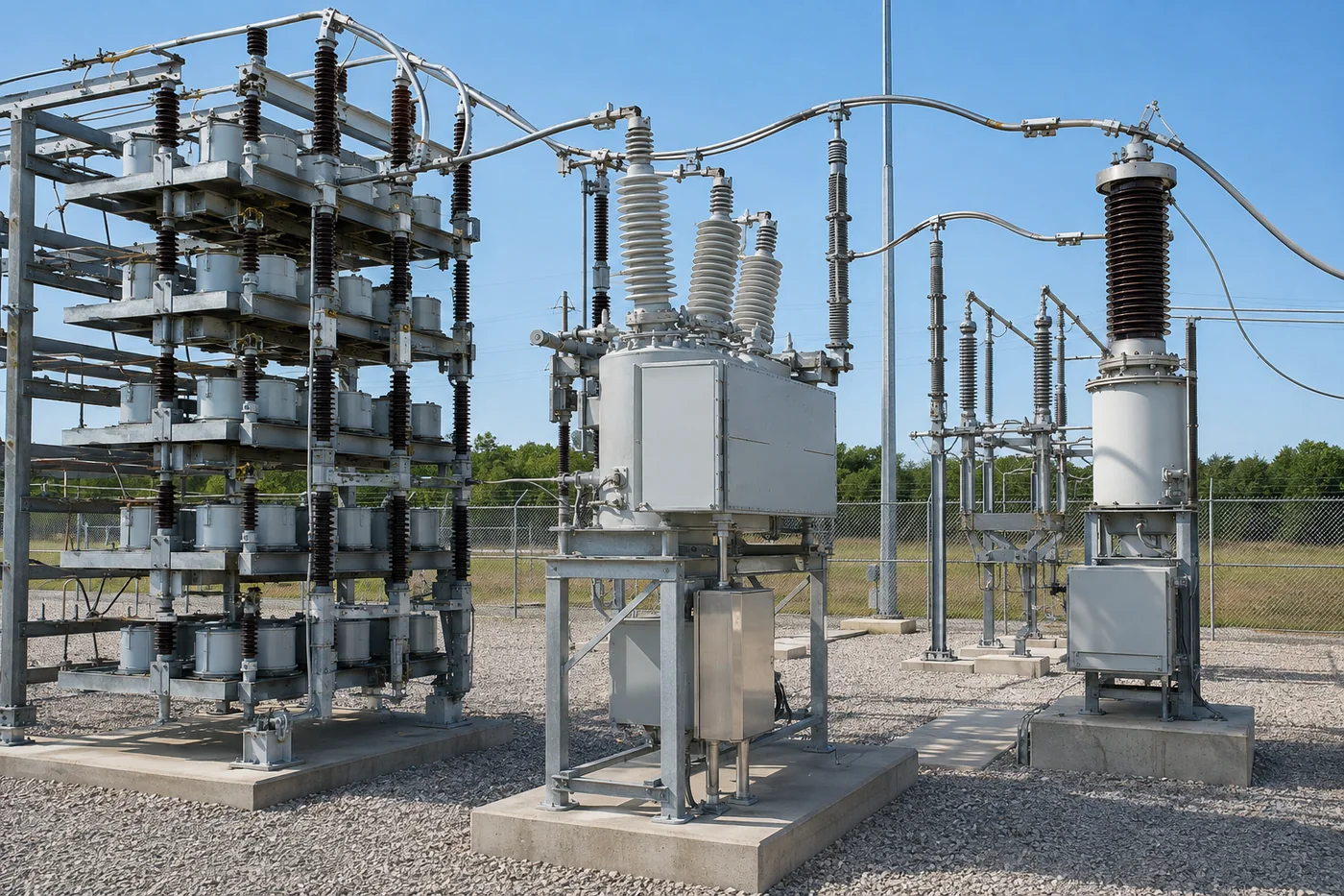
Cooling control should start auxiliaries before enabling high-loss operation, prove flow or airflow, rotate duty equipment where appropriate, and handle sensor failure safely. Define the response to one fan or pump loss, high coolant temperature, low flow, high conductivity, blocked filter, chiller failure, and station-service interruption. Controlled derating may preserve partial reactive support without exceeding component limits. Trip logic should avoid thermal damage but also avoid unnecessary loss of grid support from a transient sensor error. Validate logic using cause-and-effect tests and record the available Mvar in every degraded state.
Harmonic and Operating-Point Effects
SVC branch currents contain fundamental and, depending on topology and firing angle, harmonic components. Reactor, valve, and filter losses therefore do not always scale like a simple constant percentage of rating. Study continuous operating points, voltage extremes, firing ranges, unbalance, filter availability, and harmonic background. A cooling design verified only at nominal voltage and one Mvar output may miss the hottest condition. Confirm loss data with the equipment supplier and include tolerance. Where a filter branch is unavailable, both electrical performance and the distribution of heat among remaining branches can change.
Room and Building Integration
The SVC building must remove total equipment heat without short-circuiting supply and exhaust air. Coordinate HVAC capacity, equipment spacing, plenum design, louvers, fire dampers, acoustic treatment, access aisles, and maintenance lifting routes. Prevent condenser or radiator discharge from returning to the intake. Separate clean control spaces from dusty reactor areas where appropriate. Check auxiliary-transformer capacity and emergency supply for pumps, fans, controls, heaters, and chillers. A cooling system that works on a vendor skid can fail after installation if the building traps hot air or restricts maintenance access.
Пусконаладочные испытания
Verify sensor calibration, fan rotation, airflow direction, coolant flow, pump changeover, valve operation, conductivity, pressure, leak alarms, filter alarms, HVAC interlocks, derating, trip logic, remote indication, and loss-of-supply behavior. Perform a heat run or operating-point test adequate to demonstrate stable temperatures, allowing for thermal time constants. Record ambient, SVC output, bus voltage, branch currents, inlet and outlet temperatures, coolant data, and auxiliary states. Use these values as the healthy baseline. Investigate unexplained hot spots or temperature drift before accepting full continuous operation.
Maintenance Program
Trend temperatures at comparable Mvar and ambient conditions. Inspect and clean filters, heat exchangers, radiators, fans, pumps, strainers, and cooling passages at intervals based on actual fouling. Maintain coolant chemistry and deionization within supplier limits, test leak detection, exercise standby equipment, and inspect hoses, seals, bearings, and electrical auxiliaries. Keep spare filters, pump seals, sensors, fan assemblies, and approved coolant where lead time threatens availability. After maintenance, confirm restored flow, airflow, alarms, and automatic changeover. A documented baseline makes gradual thermal degradation visible before it causes derating.
Cooling RFQ Checklist
Provide continuous and overload Mvar duty, SVC topology, voltage and harmonic cases, component loss data, maximum and minimum ambient, altitude, solar exposure, contamination, indoor or outdoor arrangement, available cooling-water conditions, station-service reliability, acoustic limits, required redundancy, permitted derating, and maintainability constraints. Require a heat balance for normal and degraded states, equipment duty points, pump and fan curves, coolant specification, sensor list, alarm/trip matrix, auxiliary load, building heat rejection, commissioning test, maintenance intervals, and spare parts. State who owns the interface between vendor skid and site HVAC or water systems.
Related Guides
Обзор what an SVC does, SVG enclosure thermal ratings, SVG capacity selection, и CNBYG SVG products. An SVG is not the same topology as a thyristor SVC, but site thermal questions overlap.
Часто задаваемые вопросы
Как охлаждается SVC?
Принудительным воздушным охлаждением, замкнутым жидкостным охлаждением или их комбинацией с внешними теплообменниками или чиллерами, в зависимости от потерь и условий на объекте.
Зачем использовать деионизированную воду?
Контуры охлаждения клапанов могут потребовать регулируемой низкой электропроводности вблизи находящегося под напряжением силового электронного оборудования; соблюдайте предельные значения химического состава, установленные поставщиком.
Гарантирует ли N+1 полный вывод?
Нет. Полная производительность зависит от оставшихся насосов, вентиляторов, площади теплообменника, электроснабжения и рабочей точки внешней среды.
Может ли статический тиристорный компенсатор (СТК) снижать мощность вместо отключения?
Часто возможно контролируемое снижение мощности, но безопасный выходной сигнал и логика должны быть спроектированы и испытаны.
Какой тренд лучше всего отражает загрязнение?
Rising component or coolant temperature at comparable Mvar and ambient conditions is a useful early indicator.
Ссылки
- IEEE 1534 — Static Var Compensator Functional Specification Guide
- NREL — Power Electronics Thermal Management Overview
Further Learning
