Capacitor Contactor Auxiliary Resistor Failure
Capacitor contactor resistor failure can remove the intended inrush-limiting action even when the main contacts still close. Treat a damaged auxiliary resistor assembly as a switching-system fault: isolate the affected stage, verify capacitor discharge, inspect the complete contactor assembly, and investigate why it failed before returning the stage to service. A controller indication alone cannot prove that the resistor path operated correctly.
This guide helps maintenance teams distinguish an open resistor, damaged auxiliary contacts, poor connections and excessive switching duty. It does not provide a universal resistance value or authorize live measurements. The correct component ratings, switching sequence and acceptance tests come from the contactor manufacturer and the approved panel documentation.
What the auxiliary resistor assembly does
A capacitor initially presents a charging demand when connected to an AC supply. The transient depends on the supply impedance, the capacitor’s residual voltage, the point of connection and the other capacitors already connected. A contactor intended for capacitor switching may use early-making auxiliary contacts with resistors to limit the initial transient before its main contacts carry the steady current.
The physical arrangement varies between designs. Some visible loop conductors form part of a manufacturer-built resistor assembly; they should not be interpreted as ordinary interconnection wires. Replacing a damaged loop with a piece of cable can defeat the intended limiting action. Equally, a general-purpose contactor with a similar frame size is not automatically a compatible replacement.
Check the CNBYG GJ19 capacitor switching contactor against the installed assembly, but obtain the exact model documentation before assigning component values. The product photograph illustrates construction; it does not establish a universal circuit or a repair specification.
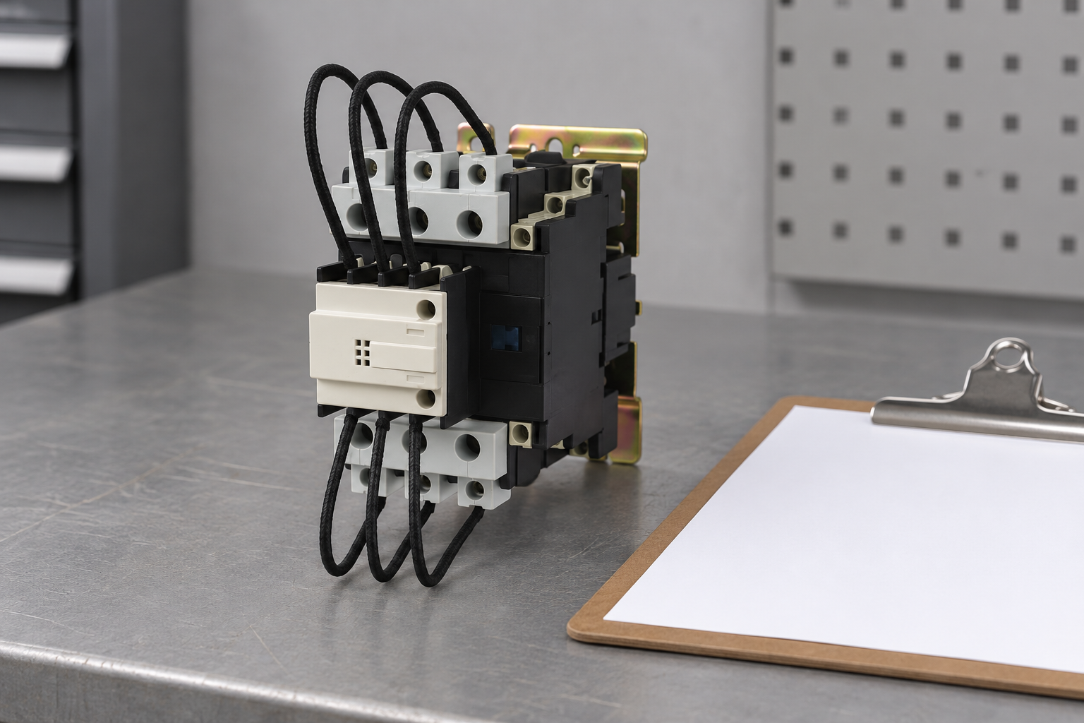
Reference-based illustration of a disconnected contactor. The image is not evidence of an actual fault or a live test.
Symptoms and what they can actually prove
A stage that produces a loud switching sound, recurrent fuse operation or unusual contact wear deserves investigation. These symptoms do not uniquely identify a resistor fault. A capacitor problem, loose connection, unsuitable protective device, excessive residual voltage or another stage switching at the same time may produce similar observations.
Record which stage operates, the controller command, the operating state of adjacent stages and the approximate load condition. Use existing monitoring records where available. If a fault happened immediately after maintenance, compare the assembly and connections with the previous approved configuration. Avoid repeatedly switching the stage to reproduce a damaging event.
| การสังเกต | Possible explanation | Useful next check with equipment isolated |
|---|---|---|
| Broken or burnt auxiliary loop | Failed resistor assembly or overheated connection | Identify the exact replacement assembly and examine its terminals |
| Main contact damage with intact-looking resistors | Auxiliary path may not make correctly | Inspect mechanical alignment and manufacturer test procedure |
| One phase behaves differently | Phase-specific connection, resistor or capacitor issue | Compare the three phase paths without assuming identical measured values |
| Several stages show repeated damage | Excessive duty or system-wide switching problem | Review delays, supply conditions and bank configuration |
| New assembly fails soon after replacement | Underlying cause remains or replacement is unsuitable | Recheck model, duty, capacitor ratings and protection coordination |
The table is a troubleshooting aid, not a fault diagnosis from appearance alone. A resistor can look intact and still be open. Conversely, a darkened surface is not sufficient evidence that its electrical characteristics are unacceptable.
Isolate safely before examining the assembly
An APFC panel can retain stored energy after the incoming supply is opened. Control circuits may also have a separate source. Identify all energy sources and follow the site’s isolation procedure before touching the contactor or its attached conductors. The ข้อกำหนดแนวปฏิบัติด้านไฟฟ้าของ OSHA address de-energization and hazardous stored electrical energy; applicable local requirements and the equipment instructions also govern the work.
Do not use the controller display, a dark indicator or a presumed elapsed delay as verification of safe conditions. Qualified personnel must verify the electrical state using the approved method. Capacitor discharge devices and waiting times need to be checked against the actual bank design. This article intentionally gives no generic wait time, terminal shorting instruction or energized probing method.
After isolation, protect nearby assemblies from accidental disturbance. Photograph the original installation and label the stage identity in the maintenance record. Keep the damaged assembly for investigation when repeated failures or warranty review make its condition important.
Inspect the complete current-limiting path
Start with the visible mechanical condition. Check whether the auxiliary assembly is properly seated, whether terminal hardware is complete and whether vibration or handling has altered its alignment. Look for cracked supports, loose fasteners, insulation damage and local discoloration. Follow the manufacturer’s torque and inspection requirements rather than tightening everything by feel.
Next, inspect the early-making contact mechanism if the design allows this without unauthorized dismantling. The resistor path relies on timing as well as continuity. An electrically sound resistor cannot limit the initial event if the auxiliary contact does not engage as intended. Worn or obstructed mechanisms may therefore require replacement of the complete assembly.
For electrical checks, use the exact manufacturer method and disconnect paths that would otherwise create parallel readings. Record the instrument, measurement conditions and component temperature where relevant. Do not compare an in-circuit resistance reading with an invented internet value. A reading obtained through other connected components can be misleading and should not be marked as a passed test.
Check the capacitor stage and switching settings
Examine the stage that the contactor serves. Confirm capacitor identity, voltage rating, connection, kvar and any associated reactor. Review whether a capacitor was recently replaced with a different type or whether additional capacitance was added. A contactor selected for an earlier stage configuration may no longer suit the actual duty.
cURL Too many subrequests by single Worker invocation. To configure this limit, refer to https://developers.cloudflare.com/workers/wrangler/configuration/#limits cURL Too many subrequests by single Worker invocation. To configure this limit, refer to https://developers.cloudflare.com/workers/wrangler/configuration/#limits cURL Too many subrequests by single Worker invocation. To configure this limit, refer to https://developers.cloudflare.com/workers/wrangler/configuration/#limits.
cURL Too many subrequests by single Worker invocation. To configure this limit, refer to https://developers.cloudflare.com/workers/wrangler/configuration/#limits cURL Too many subrequests by single Worker invocation. To configure this limit, refer to https://developers.cloudflare.com/workers/wrangler/configuration/#limits cURL Too many subrequests by single Worker invocation. To configure this limit, refer to https://developers.cloudflare.com/workers/wrangler/configuration/#limits.
cURL Too many subrequests by single Worker invocation. To configure this limit, refer to https://developers.cloudflare.com/workers/wrangler/configuration/#limits
cURL Too many subrequests by single Worker invocation. To configure this limit, refer to https://developers.cloudflare.com/workers/wrangler/configuration/#limits.
cURL Too many subrequests by single Worker invocation. To configure this limit, refer to https://developers.cloudflare.com/workers/wrangler/configuration/#limits.
After installation, inspect the downstream capacitor and the protection. Replacing the visibly burnt component without checking damaged contacts or connections can leave another failure point in service. Record the original fault hypothesis separately from confirmed findings so the maintenance history does not present an assumption as a proven cause.
Plan the return-to-service check
The acceptance plan should specify who authorizes re-energization, which interlocks must work, what records will be collected and what conditions require an immediate stop. Use the approved panel procedure and suitable instrumentation. This guide does not ask technicians to open a live cabinet or watch exposed contacts during operation.
Confirm that the controller recognizes the correct stage and that the bank’s measured response is reasonable under the test load. A relay output indicator demonstrates a command; it is not proof of the contactor’s complete switching sequence. If waveform evidence is needed to assess the transient, arrange an appropriate power-quality measurement by qualified personnel.
For related system context, read the power factor correction guide and verify that its general principles fit the specific installation. The NPTEL power quality course provides independent educational background on disturbances and correction; equipment acceptance still requires project-specific documentation.
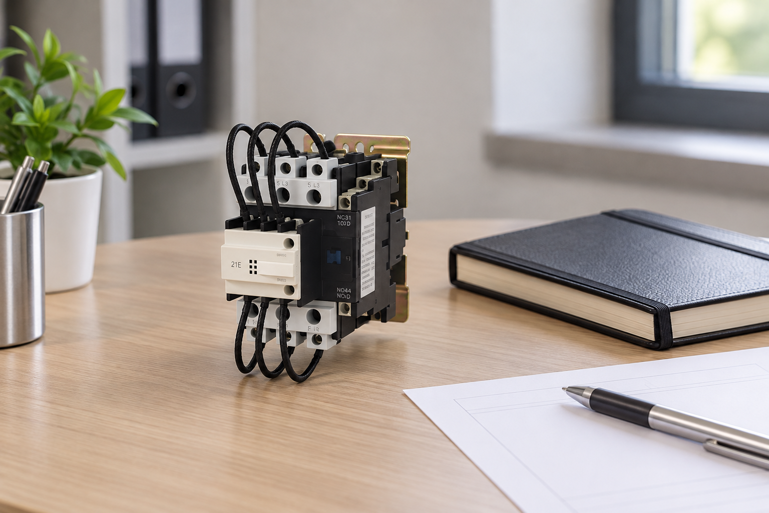
Reference-based maintenance illustration. Test results and fault records must come from the real installation.
What to put in the maintenance record
Include stage number, component identity, observed damage, isolation reference, measurement results, replacement part and the settings reviewed. Add the reason for the chosen action and any unresolved question. This allows the next technician to tell whether the resistor itself failed, whether the auxiliary mechanism was faulty, or whether switching duty exceeded the intended conditions.
For recurring incidents, compare operating counts and event times between stages. Similar damage across several assemblies may justify a wider review of the bank rather than another isolated repair. A single affected stage may point toward its local connections, capacitor condition or replacement history. Both patterns need evidence before changing the design.
การเรียนรู้เพิ่มเติม
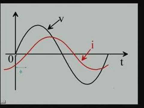
Watch Lecture – 15 Power Factor
คำถามที่มักถูกถาม
Can the main contactor still work with a failed resistor?
It may still close, but that does not establish safe or suitable capacitor switching. The intended initial current-limiting action may be lost. Keep the affected stage out of service until its assembly and underlying cause have been assessed.
Is there one resistance value for all capacitor contactors?
No. The correct assembly and test limits depend on the exact design. Use manufacturer documentation and appropriate isolated measurements instead of a generic value based on frame size or appearance.
Does adding a longer controller delay fix the resistor?
No. A suitable delay can help address premature reconnection, but it cannot restore a damaged assembly. Repair the hardware and verify discharge eligibility, switching duty and stage configuration together.
Should every contactor be replaced after one failure?
Not automatically. Inspect related stages and review operating evidence. A bank-wide issue may require broader action; an isolated fault may require a focused repair. The decision should follow findings, not a blanket replacement rule.