


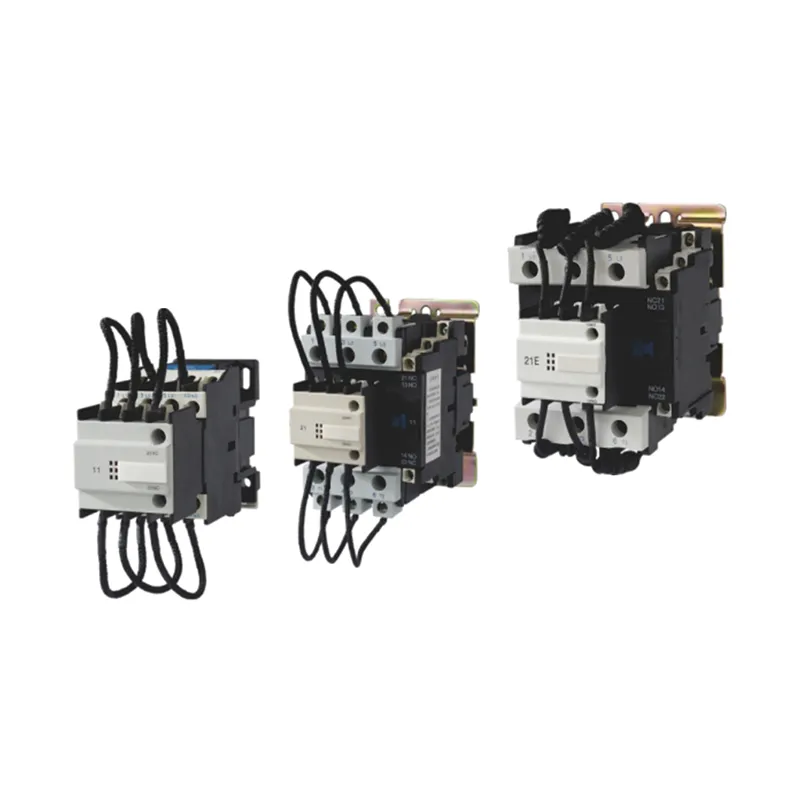
Capacitor duty contactor selection must account for capacitor-switching inrush, steady-state current, available fault level, step kvar, voltage, frequency, ambient temperature, switching rate, discharge time, upstream capacitance, and coordination with protection. A standard motor contactor with the same ampere rating is not automatically suitable. Capacitor-duty designs commonly use early-make auxiliary contacts and pre-insertion resistors or another manufacturer-defined method to limit the first transient before the main contacts close. Select from tested manufacturer tables for the complete duty, then verify coil voltage, utilization category, enclosure conditions, conductor size, protection, and control timing. Do not size from panel photographs or nominal current alone.
- Why capacitor switching is different
- Understand the pre-insertion path
- Establish the electrical duty
- Check control and mechanical details
- Coordinate discharge and reconnection
- Protection and reactor coordination
- Failure symptoms and evidence
- What to put in the purchase specification
- Factory and site acceptance evidence
- Review the contactor after an initial service period
- ตารางการตัดสินใจ
- แหล่งข้อมูลและการศึกษาเพิ่มเติม
- คำถามที่มักถูกถาม
Why capacitor switching is different
An uncharged capacitor initially presents a very low impedance to a sudden voltage difference. Closing onto the bus can therefore create a high, short-duration current limited by source impedance, conductors, reactors, resistors, and any already energized capacitors. Back-to-back switching can be more severe because an energized bank contributes to the transient. The contactor must withstand repeated making duty without contact welding, excessive erosion, nuisance operation, or damage to nearby components. The event is transient, so a clamp meter's normal current display cannot characterize it.
Understand the pre-insertion path

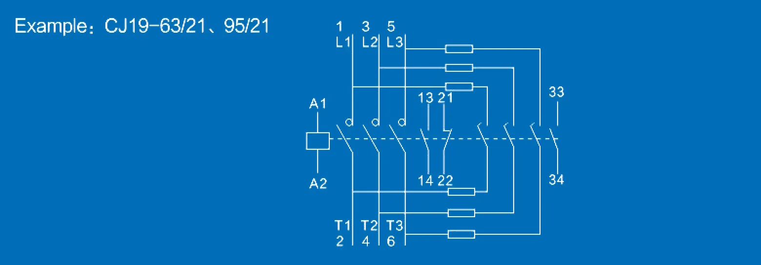
Many capacitor-duty contactors close auxiliary contacts through damping resistors before the main contacts. The temporary path limits the transient; the main contacts then carry steady current and the auxiliary path is removed from continuous duty. Exact timing and construction belong to the tested device design. Do not modify resistor values, auxiliary blocks, or mechanical linkages. Inspect replacement parts as a complete assembly. A contactor that appears physically compatible may not reproduce the intended sequence or withstand the same duty.
Establish the electrical duty
Record line voltage, frequency, capacitor step kvar at actual voltage, connection, reactor presence, prospective short-circuit current, upstream transformer, other energized banks, and expected switching frequency. Calculate balanced line current from kvar and voltage as an initial check, but use the manufacturer's capacitor-duty selection table for final device choice. Capacitor current can exceed the ideal nameplate calculation because of voltage variation, capacitance tolerance, and harmonic content. Determine whether the application is single-stage, multi-stage, or back-to-back switching and state the worst operating condition.
Check control and mechanical details
Match the coil voltage, frequency or DC specification, control-power tolerance, and controller output. Confirm auxiliary contacts needed for feedback, interlocks, and alarms. Check mounting orientation, terminal capacity, tightening torque, mechanical clearances, and replacement accessibility. The enclosure temperature can be higher than room temperature; apply the declared derating and ventilation rules. A larger frame is not a cure for incorrect coil voltage, excessive switching frequency, or poor thermal design.
ตารางการตัดสินใจ
| Selection input | Why it changes the duty | Evidence | ข้อผิดพลาดทั่วไป |
|---|---|---|---|
| Step kvar, voltage and frequency | Sets fundamental branch current | Approved bank schedule | Selecting by frame size alone |
| Already energized stages | Can create back-to-back transient contribution | Single-line and switching sequence | Assuming only source inrush matters |
| Reactor or damping method | Changes impedance and transient behavior | Approved reactor-capacitor assembly | Mixing unmatched components |
| Switching rate and minimum off-time | Affects thermal stress, wear and residual voltage | Load profile and controller settings | Using very short delays |
| Coil and enclosure conditions | Affects reliable closing and temperature rise | Control schematic and thermal design | Upsizing contacts while ignoring coil voltage |
| Protection and fault level | Defines coordination and withstand needs | Short-circuit and protection study | Treating operational inrush as the only current |
Coordinate discharge and reconnection

A disconnected capacitor retains charge until its discharge system reduces voltage. Reclosing too soon can create a large voltage difference across the switch and a more severe transient. Program the controller delay to meet the capacitor and switching assembly requirements, and verify the discharge device is present and healthy. In multi-stage panels, rotation logic should not defeat minimum off-time. The U.S. Department of Energy distinguishes fixed and switched correction according to load variation; once switching is required, the complete timing and duty cycle must be engineered.
Protection and reactor coordination
Review branch fuses or breakers, conductor ampacity, short-circuit withstand, contactor coordination, reactor thermal duty if used, and upstream protection. A detuned reactor changes branch current and transient behavior, so select the contactor for the approved reactor-capacitor assembly rather than a capacitor-only assumption. Protection should clear faults without being selected so tightly that normal charging events cause nuisance operation. Use tested combinations where required and document the coordination basis.
Failure symptoms and evidence
Welded or heavily pitted main contacts can indicate excessive inrush, failed pre-insertion components, rapid cycling, back-to-back duty beyond rating, or short reconnection delay. Overheated terminals suggest loose connections, undersized conductors, poor crimping, high ambient temperature, or continuous overcurrent. Coil chatter points to control-voltage drop or unstable commands. Repeated resistor damage may indicate the auxiliary path remains engaged incorrectly or switching exceeds its duty. Record switching count, stage current, thermal condition, command history, and component state before replacing the contactor with a larger one.
What to put in the purchase specification
Specify system voltage and frequency, stage kvar and connection, reactor details, calculated and expected current, switching arrangement, back-to-back condition, maximum operations per time period, minimum off-time, ambient and enclosure temperature, altitude if relevant, coil supply, auxiliary contacts, protection coordination, terminal and conductor requirements, standards, documentation, and acceptance tests. Request the exact capacitor-duty table and declared utilization category. This information lets the supplier select a tested device instead of guessing from an ampere value.
Factory and site acceptance evidence
At the factory, confirm device identity, wiring, terminal torque records, control sequence, auxiliary feedback, protection, and the declared capacitor-duty combination. At site, record bus voltage, stage current balance, reactive-power change, command and feedback timing, minimum off-time, temperature after representative operation, and any abnormal sound or chatter. Capturing a switching transient requires suitable bandwidth, probes, and a safe measurement plan; ordinary panel meters are not enough. Store baseline photographs and values with the commissioning record so later pitting, overheating, or nuisance trips can be compared with the accepted condition. Repeat the review after a capacitor, reactor, controller, transformer, or switching sequence changes because each can alter the duty seen by the contactor.
Review the contactor after an initial service period
A post-commissioning inspection can reveal problems that a short acceptance test misses. Under the site's approved maintenance procedure, check terminal tightness, discoloration, insulation condition, coil supply, auxiliary feedback, abnormal vibration, and temperature patterns. Review controller logs for rapid cycling, aborted commands, or operation counts above the design assumption. Compare each stage's current and kvar contribution with the baseline; a declining or unbalanced response can indicate a capacitor, fuse, connection, or reactor problem that increases contactor stress. If contact wear is inspected, use the manufacturer's acceptance criteria rather than filing, polishing, or judging appearance alone. Correct the root cause before installing a replacement, and update the duty record whenever operating schedules or upstream capacitor stages change. Document every replacement by exact device, date, stage, cause, corrective action, and final measured response.
หัวข้อนี้เชื่อมต่อกับอุปกรณ์ CNBYG อย่างไร
คู่มือนี้สนับสนุนการอภิปรายเกี่ยวกับข้อกำหนดและการตรวจรับสำหรับ Capacitor switching contactor สายผลิตภัณฑ์ ข้อมูลผลิตภัณฑ์ต้องได้รับการตรวจสอบเทียบกับแรงดันไฟฟ้าจริงของระบบ โปรไฟล์โหลด การวัดฮาร์มอนิก การออกแบบการป้องกัน สภาวะแวดล้อม และข้อกำหนดของโครงการที่เกี่ยวข้อง โปรดแชร์ไดอะกรัมเส้นเดียว (Single-line diagram) และข้อมูลการวัดที่เป็นตัวแทน ก่อนที่จะขอคำแนะนำเกี่ยวกับรุ่นผลิตภัณฑ์.
คู่มือวิศวกรรม CNBYG ที่เกี่ยวข้อง
- compare a power contactor and capacitor-duty contactor
- understand point-on-wave capacitor switching
- review contactor duty in harmonic networks
แหล่งข้อมูลและการศึกษาเพิ่มเติม
เดอะ คู่มือระบบขับเคลื่อนด้วยมอเตอร์ของกระทรวงพลังงานสหรัฐอเมริกา การแก้ไขตัวประกอบกำลังแบบคงที่ (Fixed Power-Factor Correction) และแบบสับเปลี่ยนอัตโนมัติ (Automatically Switched Power-Factor Correction) เหมาะกับรูปแบบโหลดทางอุตสาหกรรมที่แตกต่างกัน ดังนี้ครับ: **1. การแก้ไขตัวประกอบกำลังแบบคงที่ (Fixed PFC)** * **เหมาะสำหรับ:** โหลดอุตสาหกรรมที่มีลักษณะคงที่ (Constant Load) ทำงานตลอดเวลา หรือมีการเปลี่ยนแปลงน้อยมาก * **รูปแบบโหลดที่เหมาะสม:** * มอเตอร์ขนาดใหญ่ตัวเดียวที่ทำงานต่อเนื่องเป็นเวลานาน * โรงงานที่มีกะการทำงานเดียว และมีการเปิดใช้อุปกรณ์ไฟฟ้าในปริมาณที่สม่ำเสมอ * **จุดติดตั้ง:** มักต่อตรงเข้ากับขั้วของมอเตอร์ตัวนั้นๆ หรือที่ตู้เมนหลักของโรงงานขนาดเล็กที่ไม่ซับซ้อน **2. การแก้ไขตัวประกอบกำลังแบบสับเปลี่ยนอัตโนมัติ (Automatically Switched PFC)** * **เหมาะสำหรับ:** โหลดอุตสาหกรรมที่มีการเปลี่ยนแปลงขึ้น-ลงตลอดเวลา (Fluctuating Load) มีหลายแผนก หรือมีการเปิด-ปิดเครื่องจักรไม่พร้อมกัน * **รูปแบบโหลดที่เหมาะสม:** * โรงงานขนาดกลางถึงใหญ่ที่มีสายการผลิตหลากหลาย * กระบวนการผลิตที่มีมอเตอร์หรือเครื่องจักรขนาดใหญ่หลายตัวสลับกันทำงาน ทำให้ความต้องการพลังงานรีแอกทีฟ (Reactive Power) เปลี่ยนแปลงตลอดทั้งวัน * **จุดติดตั้ง:** ติดตั้งที่ตู้เมนสวิตช์บอร์ดหลัก (Main Distribution Board - MDB) ของโรงงาน โดยระบบจะคอยตรวจวัดค่า Power Factor แบบเรียลไทม์ และสั่งตัดต่อชุดตัวเก็บประจุ (Capacitor Bank) เข้า-ออกโดยอัตโนมัติเพื่อให้ค่า PF อยู่ในเกณฑ์ที่กำหนดตลอดเวลา. OSHA 1910.333 เป็นแนวทางพื้นฐานของสหรัฐอเมริกาสำหรับการตัดกระแสไฟฟ้าและแนวปฏิบัติในการทำงานเกี่ยวกับไฟฟ้า. IEEE 519 คือข้อมูลอ้างอิงจากหน่วยงานกำหนดมาตรฐานสำหรับการควบคุมฮาร์มอนิก ณ จุดบรรจบร่วม (PCC) ให้ใช้มาตรฐานฉบับปัจจุบันและข้อกำหนดท้องถิ่นสำหรับโครงการนี้.

การเรียนรู้เพิ่มเติม: MIT OpenCourseWare บรรยายที่ 4: ตัวประกอบกำลัง. การบรรยายของ MIT อธิบายเรื่องตัวประกอบกำลังและความเพี้ยน แต่ไม่ได้ใช้แทนคำแนะนำเกี่ยวกับอุปกรณ์เฉพาะของโครงการ.
คำถามที่มักถูกถาม
Can a normal contactor switch a capacitor bank?
Use only a device and rating explicitly approved for the capacitor-switching duty. An equal motor-current rating is not sufficient evidence.
Why do capacitor contactors use resistors?
In designs with pre-insertion resistors, they temporarily limit the closing transient before the main contacts carry steady current.
How is capacitor contactor current calculated?
For a balanced three-phase branch, ideal current is Q divided by √3 times line voltage, but final selection needs manufacturer duty tables and application factors.
Why is minimum off-time important?
It allows the capacitor to discharge before reconnection, reducing the voltage difference and transient stress.
บันทึกทางวิศวกรรมฉบับสุดท้าย: ให้ถือว่าสูตรคำนวณและรายการตรวจสอบเป็นเครื่องมือในการคัดกรอง การติดตั้ง การป้องกัน การทดสอบการใช้งาน และการทดสอบขณะมีกระแสไฟฟ้า จะต้องดำเนินการโดยบุคลากรที่มีคุณสมบัติเหมาะสม โดยใช้แบบที่ได้รับอนุมัติ คู่มือผลิตภัณฑ์ การศึกษา และขั้นตอนความปลอดภัยของหน้างาน.