


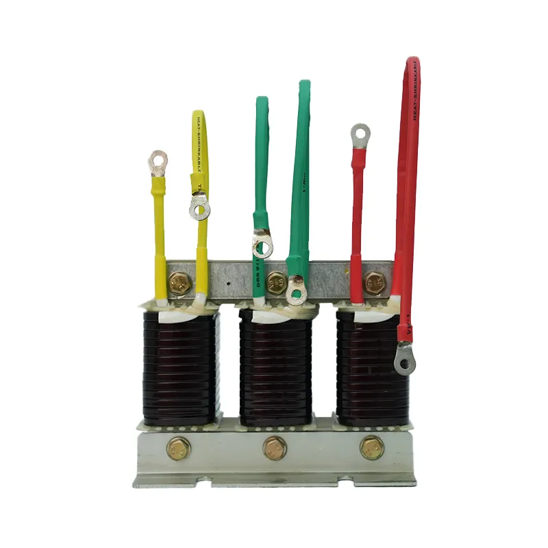
A detuned reactor calculation starts with the required fundamental-frequency kvar, system voltage and frequency, capacitor connection, selected detuning factor, and measured harmonic environment. The detuning factor is the ratio of reactor reactance to capacitor reactance at the fundamental frequency. From it, the ideal series-resonance frequency is approximately the system frequency divided by the square root of that ratio. This calculation is only the first design screen. The capacitor voltage rises when a reactor is added, component tolerances move the actual tuning point, and the network can contain parallel resonances. Verify the result with manufacturer data, a harmonic study, thermal and fault-duty checks, and the applicable project standards before ordering equipment.
- What detuning is intended to do
- Define the detuning factor
- Calculate branch current and reactor reactance
- Account for capacitor voltage rise
- Use measured harmonics and network impedance
- Check tolerances and aging
- Coordinate switching and protection
- Calculation workflow and deliverables
- Worked screening example and limits
- Verify the installed branch after energization
- ตารางการตัดสินใจ
- แหล่งข้อมูลและการศึกษาเพิ่มเติม
- คำถามที่มักถูกถาม
What detuning is intended to do
A series reactor changes the impedance of a capacitor branch so its series-resonance frequency lies below a troublesome harmonic order. Above that frequency, the branch behaves inductively rather than as an attractive low-impedance path for higher-order harmonic current. Detuning is primarily a protection and resonance-control strategy for power factor correction banks; it is not automatically a tuned harmonic filter with a guaranteed current-absorption target. The design objective, harmonic spectrum, bus impedance, and acceptance criteria must be stated before selecting a percentage.
Define the detuning factor

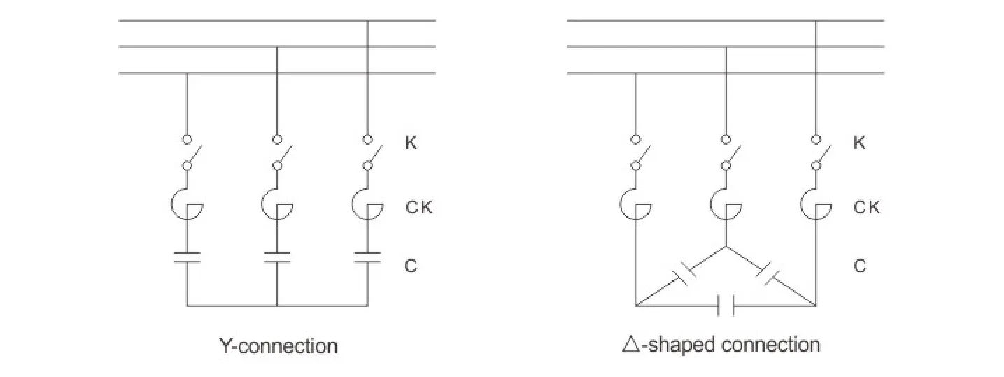
Let p equal XL divided by XC at the fundamental frequency, expressed as a decimal. XL is the reactor reactance and XC is the magnitude of capacitor reactance in the series branch. The ideal resonance frequency is fr = f1 / sqrt(p), where f1 is the system frequency. For example, p = 0.07 on a 50 Hz system gives an ideal value near 189 Hz. That arithmetic does not authorize a 7 percent reactor for every plant. It only shows the nominal relationship. Actual reactors and capacitors have tolerance, temperature dependence, and manufacturing limits, while the network has its own frequency-dependent impedance.
Calculate branch current and reactor reactance
For a balanced three-phase branch, begin from the capacitor bank's required kvar at the bus and identify whether the quoted rating refers to the capacitor alone or the complete reactor-capacitor assembly. The fundamental branch impedance is the net capacitive reactance after subtracting reactor reactance. If the assembly kvar and line voltage are known, calculate line current using I = Q / (sqrt(3) × VLL) for a balanced three-phase load. Derive the net per-phase impedance using the actual delta or wye connection, then separate XL and XC using the selected p. Because rating conventions differ, reconcile the hand calculation with the supplier's complete assembly tables.
Account for capacitor voltage rise
The reactor causes the capacitor terminal voltage to exceed the bus contribution under fundamental-frequency operation. A simplified ideal relationship indicates that capacitor voltage increases as the detuning factor grows. The capacitor must therefore be selected for the actual continuous voltage and current stress, including system voltage tolerance, harmonic current, temperature, and manufacturing tolerance. Do not pair a reactor with a capacitor based only on nominal bus voltage and kvar. Request the approved reactor-capacitor combination and its declared assembly output.
ตารางการตัดสินใจ
| Input or result | Symbol or example | ทำไมจึงสำคัญ | Verification |
|---|---|---|---|
| System frequency | f1 | Sets harmonic frequencies and resonance calculation | Nameplate and measured frequency |
| Detuning factor | p = XL/XC | Defines nominal reactor-to-capacitor reactance ratio | Project study and approved assembly |
| Ideal series resonance | fr = f1/√p | First screen for location below a harmonic order | Recalculate with tolerances |
| Assembly reactive power | Q | Determines branch current and compensation delivered | Clarify capacitor-only vs assembly rating |
| Three-phase line current | I = Q/(√3 × VLL) | Supports conductor and switch review for balanced operation | Compare with approved manufacturer data |
| Harmonic spectrum and network impedance | Measured/modelled data | Reveals branch stress and parallel resonance risk | Power-quality study at representative loads |
Use measured harmonics and network impedance

A percentage selected from habit may move resonance into an unfavorable region. Collect voltage and current harmonic spectra under representative operating states, transformer and generator impedances, cable data where material, existing bank details, drive and converter information, and utility background distortion. Model both the series branch and possible parallel resonance with the network. IEEE 519 defines harmonic evaluation at the point of common coupling, but equipment design also needs local branch currents and voltages. A compliance limit at the PCC is not a component-sizing rule.
Check tolerances and aging
Capacitance can change with tolerance, temperature, service aging, and failed internal elements. Reactor inductance also has tolerance and may change with current if its magnetic design approaches saturation. These shifts change the resonance frequency and current distribution. Evaluate the worst credible combination, not only nominal values. Acceptance testing can include inductance, capacitance, resistance, insulation, phase balance, and current measurements as appropriate to the equipment and procedures. Maintain baseline values so later inspection can identify drift.
Coordinate switching and protection
A detuned branch has switching transients, discharge requirements, inrush behavior, and fault energy that affect the contactor or switch, fuses, breakers, conductors, and controller timing. Confirm capacitor-duty switching, reactor thermal protection where provided, overcurrent coordination, enclosure ventilation, and safe discharge before reconnection. A reactor does not replace short-circuit protection or a switching-device duty review. If stages have unequal ratings, document each reactor-capacitor pair and prevent field substitution with an unmatched component.
Calculation workflow and deliverables
The design file should state system voltage and frequency, required assembly kvar, connection, selected p and rationale, ideal fr, capacitor and reactor ratings, calculated fundamental current, voltage rise basis, harmonic study cases, component tolerances, thermal limits, protection, switching duty, and acceptance measurements. Add the supplier's approved combination data and drawing references. Recalculate after changes to transformer size, generator operation, large nonlinear loads, existing capacitors, or stage ratings. The deliverable is a verified branch design, not merely a percentage and a frequency.
Worked screening example and limits
For a 50 Hz system with p = 0.07, the ideal screening calculation gives fr = 50 / √0.07, or approximately 189 Hz. For a balanced 100 kvar assembly at 400 V, the ideal line-current screen is 100,000 / (√3 × 400), or approximately 144 A. These two values are not a purchase specification. The declared assembly kvar may differ from the capacitor nameplate rating, capacitor voltage rises across the series combination, harmonic current increases RMS stress, and tolerances shift resonance. Use the example only to check units and order of magnitude, then substitute the project study and approved manufacturer combination.
Verify the installed branch after energization
Measure line voltage, phase currents, current balance, active and reactive power, and capacitor terminal voltage where the approved procedure permits. Compare the measured reactive-power change with the declared assembly output at actual voltage. Review harmonic current in the reactor-capacitor branch and bus voltage distortion during representative load states, not only immediately after energization. Use thermal imaging or temperature sensors after sufficient loading time and compare phases. Listen for abnormal reactor noise while recognizing that sound alone is not a diagnostic measurement. Confirm the controller's minimum off-time and stage sequence, then preserve the initial capacitance, inductance, resistance, current, temperature, and harmonic records. A later increase in current or temperature can then be evaluated against a documented baseline instead of an assumed normal condition.
หัวข้อนี้เชื่อมต่อกับอุปกรณ์ CNBYG อย่างไร
คู่มือนี้สนับสนุนการอภิปรายเกี่ยวกับข้อกำหนดและการตรวจรับสำหรับ Series reactor สายผลิตภัณฑ์ ข้อมูลผลิตภัณฑ์ต้องได้รับการตรวจสอบเทียบกับแรงดันไฟฟ้าจริงของระบบ โปรไฟล์โหลด การวัดฮาร์มอนิก การออกแบบการป้องกัน สภาวะแวดล้อม และข้อกำหนดของโครงการที่เกี่ยวข้อง โปรดแชร์ไดอะกรัมเส้นเดียว (Single-line diagram) และข้อมูลการวัดที่เป็นตัวแทน ก่อนที่จะขอคำแนะนำเกี่ยวกับรุ่นผลิตภัณฑ์.
คู่มือวิศวกรรม CNBYG ที่เกี่ยวข้อง
- why series reactors are used in capacitor banks
- select detuning reactors from harmonic network evidence
- troubleshoot harmonic resonance after switching
แหล่งข้อมูลและการศึกษาเพิ่มเติม
เดอะ คู่มือระบบขับเคลื่อนด้วยมอเตอร์ของกระทรวงพลังงานสหรัฐอเมริกา การแก้ไขตัวประกอบกำลังแบบคงที่ (Fixed Power-Factor Correction) และแบบสับเปลี่ยนอัตโนมัติ (Automatically Switched Power-Factor Correction) เหมาะกับรูปแบบโหลดทางอุตสาหกรรมที่แตกต่างกัน ดังนี้ครับ: **1. การแก้ไขตัวประกอบกำลังแบบคงที่ (Fixed PFC)** * **เหมาะสำหรับ:** โหลดอุตสาหกรรมที่มีลักษณะคงที่ (Constant Load) ทำงานตลอดเวลา หรือมีการเปลี่ยนแปลงน้อยมาก * **รูปแบบโหลดที่เหมาะสม:** * มอเตอร์ขนาดใหญ่ตัวเดียวที่ทำงานต่อเนื่องเป็นเวลานาน * โรงงานที่มีกะการทำงานเดียว และมีการเปิดใช้อุปกรณ์ไฟฟ้าในปริมาณที่สม่ำเสมอ * **จุดติดตั้ง:** มักต่อตรงเข้ากับขั้วของมอเตอร์ตัวนั้นๆ หรือที่ตู้เมนหลักของโรงงานขนาดเล็กที่ไม่ซับซ้อน **2. การแก้ไขตัวประกอบกำลังแบบสับเปลี่ยนอัตโนมัติ (Automatically Switched PFC)** * **เหมาะสำหรับ:** โหลดอุตสาหกรรมที่มีการเปลี่ยนแปลงขึ้น-ลงตลอดเวลา (Fluctuating Load) มีหลายแผนก หรือมีการเปิด-ปิดเครื่องจักรไม่พร้อมกัน * **รูปแบบโหลดที่เหมาะสม:** * โรงงานขนาดกลางถึงใหญ่ที่มีสายการผลิตหลากหลาย * กระบวนการผลิตที่มีมอเตอร์หรือเครื่องจักรขนาดใหญ่หลายตัวสลับกันทำงาน ทำให้ความต้องการพลังงานรีแอกทีฟ (Reactive Power) เปลี่ยนแปลงตลอดทั้งวัน * **จุดติดตั้ง:** ติดตั้งที่ตู้เมนสวิตช์บอร์ดหลัก (Main Distribution Board - MDB) ของโรงงาน โดยระบบจะคอยตรวจวัดค่า Power Factor แบบเรียลไทม์ และสั่งตัดต่อชุดตัวเก็บประจุ (Capacitor Bank) เข้า-ออกโดยอัตโนมัติเพื่อให้ค่า PF อยู่ในเกณฑ์ที่กำหนดตลอดเวลา. OSHA 1910.333 เป็นแนวทางพื้นฐานของสหรัฐอเมริกาสำหรับการตัดกระแสไฟฟ้าและแนวปฏิบัติในการทำงานเกี่ยวกับไฟฟ้า. IEEE 519 คือข้อมูลอ้างอิงจากหน่วยงานกำหนดมาตรฐานสำหรับการควบคุมฮาร์มอนิก ณ จุดบรรจบร่วม (PCC) ให้ใช้มาตรฐานฉบับปัจจุบันและข้อกำหนดท้องถิ่นสำหรับโครงการนี้.

การเรียนรู้เพิ่มเติม: MIT OpenCourseWare บรรยายที่ 4: ตัวประกอบกำลัง. การบรรยายของ MIT อธิบายเรื่องตัวประกอบกำลังและความเพี้ยน แต่ไม่ได้ใช้แทนคำแนะนำเกี่ยวกับอุปกรณ์เฉพาะของโครงการ.
คำถามที่มักถูกถาม
What does a 7 percent detuned reactor mean?
Nominally, reactor reactance is 7 percent of capacitor reactance at the fundamental frequency. It does not by itself define a safe application.
How is detuned resonance frequency calculated?
For an ideal series branch, use fr = f1 divided by the square root of p, with p entered as a decimal.
Does a detuned reactor remove all harmonics?
No. It changes branch impedance and helps avoid resonance. Harmonic filtering performance requires a defined study and design objective.
Why must capacitor voltage rating be reviewed?
The series reactor increases capacitor terminal voltage and harmonic current can add stress, so bus voltage alone is insufficient.
บันทึกทางวิศวกรรมฉบับสุดท้าย: ให้ถือว่าสูตรคำนวณและรายการตรวจสอบเป็นเครื่องมือในการคัดกรอง การติดตั้ง การป้องกัน การทดสอบการใช้งาน และการทดสอบขณะมีกระแสไฟฟ้า จะต้องดำเนินการโดยบุคลากรที่มีคุณสมบัติเหมาะสม โดยใช้แบบที่ได้รับอนุมัติ คู่มือผลิตภัณฑ์ การศึกษา และขั้นตอนความปลอดภัยของหน้างาน.