How to Test a Power Capacitor with a Multimeter
A multimeter can help check an isolated power capacitor’s capacitance when its range, method and the unit’s internal connection are suitable. It cannot by itself establish insulation integrity, correct high-voltage operation, discharge safety or fitness for service in a compensation bank. Testing starts with qualified isolation and stored-energy control, then identification of what the instrument actually measures. This guide explains how to interpret an offline measurement without confusing a three-phase power capacitor with a small two-terminal electronic component.
Decide what the test must answer
Write the fault question before choosing the instrument. Has the branch lost reactive output, does one phase draw less current, or is there visible damage? A capacitance measurement answers a narrower question than a complete failure investigation. A healthy capacitance result does not clear a damaged enclosure or unreliable discharge path. An abnormal result also does not prove that every part of the bank has failed.
Use the original commissioning record where possible. Compare the same test method, terminal pairs, instrument settings and unit condition over time. A changing method can create an apparent trend that belongs to the measurement rather than the capacitor. Keep operational measurements and offline measurements as separate evidence sets, then reconcile them before approving replacement.
Isolation is a separate qualified operation
Do not connect a meter in capacitance mode to an energized bank. Opening a contactor or observing zero branch current does not establish safe access. The installation can retain charge and can have other energy sources. The documented procedure must address isolation, discharge, verification and any required grounding. แนวปฏิบัติงานด้านไฟฟ้าของ OSHA describe hazardous stored-energy control and verification requirements in their jurisdiction.
This article does not prescribe a field discharge tool, a universal waiting time or a safe residual-voltage threshold. A capacitance function is not a voltage-verification function. Qualified personnel must use suitable instruments for each task under the approved procedure. Consult the capacitor-bank safety requirements before treating a removed component as safe to handle.
Read the nameplate and connection diagram
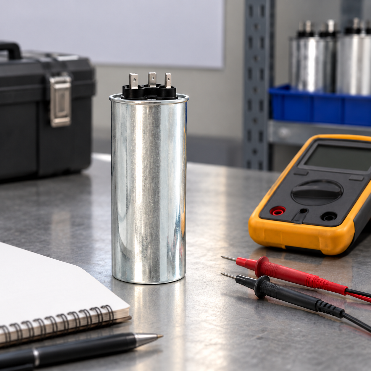
Record rated frequency, voltage, kvar, capacitance if stated, number of terminals, internal connection and discharge arrangement. The CNBYG BSMJ cylindrical power capacitor page identifies a relevant product family for an enquiry; the installed model’s own documents determine the measurement method. Do not transfer a test value from another unit merely because the cases look similar.
Three accessible terminals can belong to an internally connected three-phase assembly. A meter across two terminals measures the equivalent network between those points. It does not automatically read one internal element’s capacitance. Internal discharge resistors can influence the result, and external parallel wiring can add other capacitors. Document the arrangement before separating connections under the qualified procedure.
Check the instrument’s actual capability
Read the meter manual for capacitance range, accuracy, resolution, test method and limitations. A unit beyond the range may produce an overload indication, a slow response or no useful result. That outcome is not proof of zero capacitance. A small change near the measurement uncertainty cannot support a confident aging diagnosis. Check the instrument and leads as its manual specifies before interpreting an unexpected reading.
Lead and fixture effects become relevant when the measurement is sensitive to small changes. Use a consistent arrangement and the manufacturer’s prescribed compensation or zero function when applicable. Record the instrument identity, settings and environmental conditions. If repeated results vary substantially, resolve that variation rather than averaging unstable readings into a plausible-looking value.
Match the measurement to the internal network
For an ideal, isolated delta network with three equal element capacitances C and no other connected paths, measuring between two line terminals with the third floating gives C plus the series combination of the other two: an equivalent 1.5C. For an ideal equal star network with an inaccessible floating neutral, a line-to-line measurement gives two elements in series: C/2. These are circuit-model results, not automatic instructions for every commercial unit.
Actual construction, discharge components, tolerance and the instrument’s method can change the interpretation. Obtain the manufacturer’s expected terminal-pair measurement and conditions. The underlying series and parallel capacitor relationships are taught in OpenStax’s capacitor combinations section. A mismatch between an element value and terminal equivalent is a common reason for an apparently incorrect test.
A useful measurement record
The following table specifies information to retain, not universal pass limits. IEC 60831-1 covers the relevant self-healing low-voltage shunt capacitor standards family. The supplied product documents and applicable test requirements determine acceptance.
| Record item | ทำไมจึงสำคัญ | What to retain |
|---|---|---|
| Unit identification | Links the reading to the correct design | Model, serial, ratings and original connection diagram |
| Isolation and access | Separates safety verification from measurement | Approved procedure and qualified work record |
| Terminal pair | Defines the network seen by the meter | Pair names and status of the other terminal or neutral |
| External paths | Parallel components can alter the result | Confirmed wiring condition and discharge arrangement |
| Instrument | Determines range and uncertainty | Identity, mode, range, lead preparation and accuracy basis |
| Result and decision | Supports later comparison | Repeat readings, units, expected value and acceptance source |
Interpret all phase pairs together
When the approved method calls for terminal-pair measurements, retain each pair rather than one selected result. An imbalance can provide evidence of an internal or connection problem. However, pair readings combine internal elements, so the relationship between a faulty element and measured pairs requires the correct circuit model. Do not label one internal phase from a single pair result without that analysis.
Repeat unexpected results using the same stable conditions and an appropriate instrument. Compare with the baseline, manufacturer criteria and the uncertainty of the measurement. A nominally identical spare can be useful context when its identity and condition are known, but it cannot replace acceptance criteria. Keep visually damaged units out of service even when one capacitance reading appears close to nominal.
Use kvar and current only with the right assumptions
At fixed frequency and applied voltage, ideal capacitor reactive power is proportional to capacitance. In an uncomplicated capacitor branch, lower fundamental current can therefore support a capacitance-loss hypothesis. Real bank readings also depend on stage switching, fuse continuity, phase voltage, internal connection and any series reactor. A controller’s kvar indication alone cannot separate those causes.
Check operating evidence against the offline result. If capacitance appears normal but branch output is absent, investigate the fuse, switching and actual command response. If both indicate a reduction, determine whether the voltage and connection assumptions are valid before attributing it to aging. The reactor-in-capacitor-bank guide explains why a detuned branch needs more than a bare-capacitor calculation.
Understand what a resistance reading cannot prove
Some informal tutorials describe a resistance-mode charging movement as a capacitor test. Such an observation is not a complete capacitance or insulation acceptance test for an industrial power capacitor. Internal resistors, meter behaviour and circuit paths affect it. Never conclude that an assembly is fit for service merely because the reading rises, falls or changes as expected in a small-component demonstration.
An insulation or dielectric test requires its own approved equipment, method and acceptance criteria. Applying an improvised test voltage can damage the assembly or create a new hazard. Ask the manufacturer which tests are appropriate for the supplied design and whether connected accessories must be considered. Keep these results separate from the multimeter capacitance result in the work order.

Turn the result into a defensible work order
Do not lose the raw measurements when transferring the conclusion to a work order. Keep every tested pair, unsuccessful readings and the reason for any repeat. If a second instrument gives a different result, document its range and method before choosing the more convenient answer. That record allows another engineer to reproduce the comparison and identify whether the disagreement comes from the circuit, the meter or the test conditions.
State the result with its units, method and comparison basis. A useful conclusion is that the measured terminal equivalent differs from the documented expectation under stated conditions. A weak conclusion is simply that the capacitor is bad. Identify whether the discrepancy is repeatable, whether damage or imbalance exists and what further investigation remains unresolved.
If replacement is approved, retain the original rating, connection, dimensions, reactor and protection details. Verify the new assembly through the approved installation and operational checks. Enter the baseline in the capacitor-bank maintenance checklist records so future measurements have a meaningful reference. A successful offline test is one part of that acceptance, not the complete return-to-service decision.
Educational video: capacitor measurement concepts
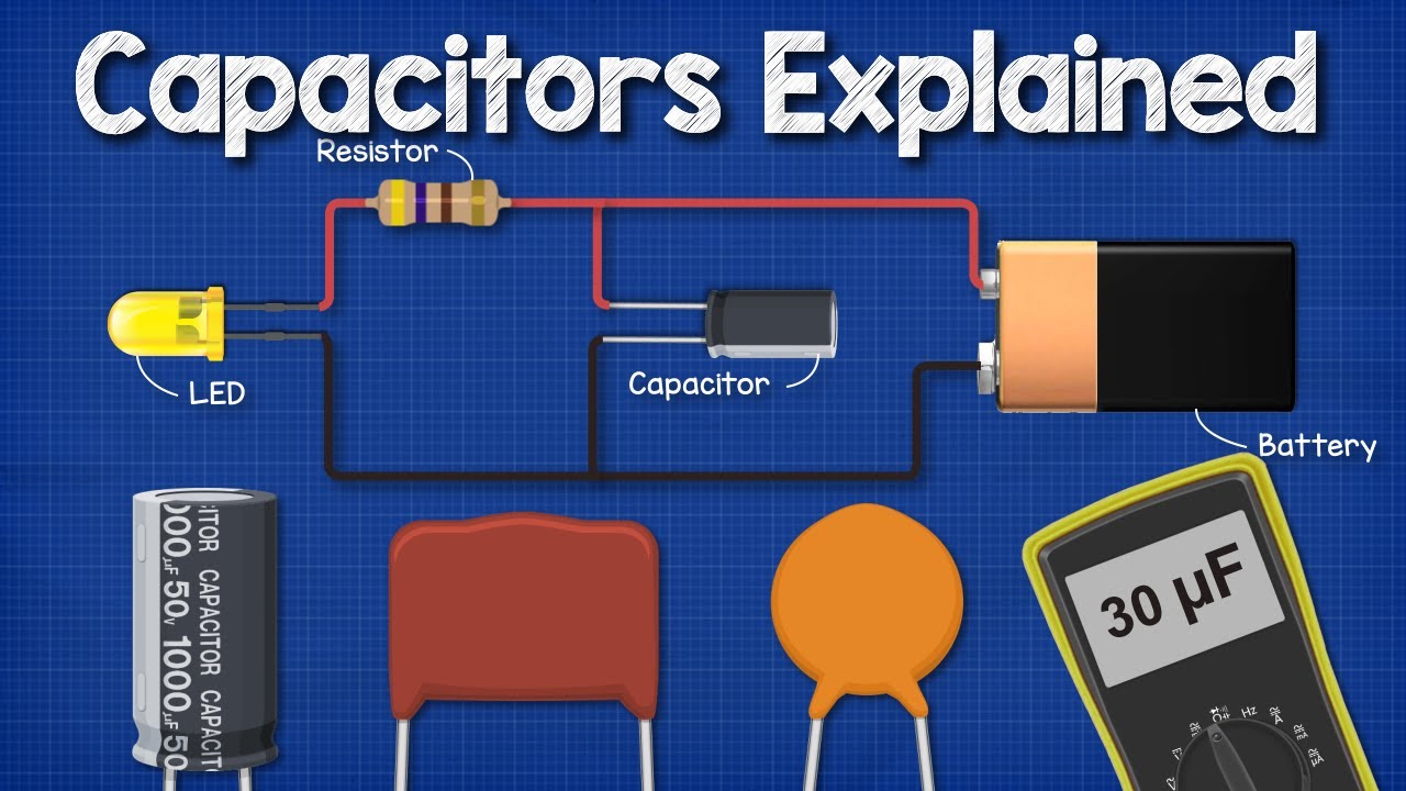
The Engineering Mindset introduces capacitor behaviour and basic measurement. Its demonstrations explain concepts using small components; they do not authorize access to, discharge of or testing of an industrial bank. The qualified procedure and equipment-specific method govern the actual work.
คำถามที่มักถูกถาม
Can any multimeter test a power capacitor?
No. Its capacitance range, accuracy and method must suit the unit and the approved measurement. An out-of-range indication is not evidence of an open capacitor.
Is the line-to-line reading the nameplate capacitance?
Not necessarily. Internal star or delta elements and discharge paths can change the equivalent seen between terminals. Obtain the product-specific expected value.
Does a good capacitance reading prove the unit is safe?
No. It does not independently establish insulation, discharge function, physical integrity or operational suitability. Those require their own acceptance evidence.
What should accompany a failed measurement?
Keep unit identity, connection, terminal pair, instrument, repeat results, uncertainty and acceptance source. Link that record to the qualified safety procedure and operational fault evidence.