Detuned Reactor Calculation for Capacitor Banks
A detuned reactor calculation starts with the required fundamental-frequency kvar, system voltage and frequency, capacitor connection, selected detuning factor, and measured harmonic environment. The detuning factor is the ratio of reactor reactance to capacitor reactance at the fundamental frequency. From it, the ideal series-resonance frequency is approximately the system frequency divided by the square root of that ratio. This calculation is only the first design screen. The capacitor voltage rises when a reactor is added, component tolerances move the actual tuning point, and the network can contain parallel resonances. Verify the result with manufacturer data, a harmonic study, thermal and fault-duty checks, and the applicable project standards before ordering equipment.
- What detuning is intended to do
- Define the detuning factor
- Calculate branch current and reactor reactance
- Account for capacitor voltage rise
- Use measured harmonics and network impedance
- Check tolerances and aging
- Coordinate switching and protection
- Calculation workflow and deliverables
- Worked screening example and limits
- Verify the installed branch after energization
- Karar tablosu
- Kaynaklar ve daha fazla okuma
- Sık sorulan sorular
What detuning is intended to do
A series reactor changes the impedance of a capacitor branch so its series-resonance frequency lies below a troublesome harmonic order. Above that frequency, the branch behaves inductively rather than as an attractive low-impedance path for higher-order harmonic current. Detuning is primarily a protection and resonance-control strategy for power factor correction banks; it is not automatically a tuned harmonic filter with a guaranteed current-absorption target. The design objective, harmonic spectrum, bus impedance, and acceptance criteria must be stated before selecting a percentage.
Define the detuning factor
Let p equal XL divided by XC at the fundamental frequency, expressed as a decimal. XL is the reactor reactance and XC is the magnitude of capacitor reactance in the series branch. The ideal resonance frequency is fr = f1 / sqrt(p), where f1 is the system frequency. For example, p = 0.07 on a 50 Hz system gives an ideal value near 189 Hz. That arithmetic does not authorize a 7 percent reactor for every plant. It only shows the nominal relationship. Actual reactors and capacitors have tolerance, temperature dependence, and manufacturing limits, while the network has its own frequency-dependent impedance.
Calculate branch current and reactor reactance
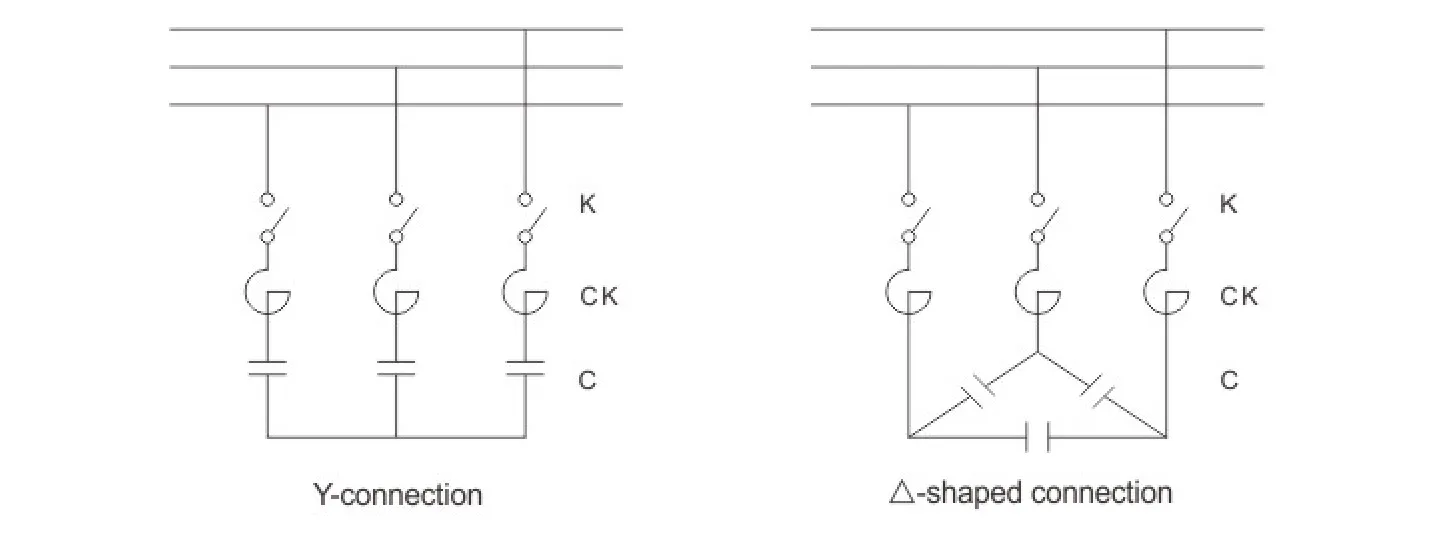
For a balanced three-phase branch, begin from the capacitor bank's required kvar at the bus and identify whether the quoted rating refers to the capacitor alone or the complete reactor-capacitor assembly. The fundamental branch impedance is the net capacitive reactance after subtracting reactor reactance. If the assembly kvar and line voltage are known, calculate line current using I = Q / (sqrt(3) × VLL) for a balanced three-phase load. Derive the net per-phase impedance using the actual delta or wye connection, then separate XL and XC using the selected p. Because rating conventions differ, reconcile the hand calculation with the supplier's complete assembly tables.
Account for capacitor voltage rise
The reactor causes the capacitor terminal voltage to exceed the bus contribution under fundamental-frequency operation. A simplified ideal relationship indicates that capacitor voltage increases as the detuning factor grows. The capacitor must therefore be selected for the actual continuous voltage and current stress, including system voltage tolerance, harmonic current, temperature, and manufacturing tolerance. Do not pair a reactor with a capacitor based only on nominal bus voltage and kvar. Request the approved reactor-capacitor combination and its declared assembly output.
Karar tablosu
| Input or result | Symbol or example | Neden önemli | Verification |
|---|---|---|---|
| System frequency | f1 | Sets harmonic frequencies and resonance calculation | Nameplate and measured frequency |
| Detuning factor | p = XL/XC | Defines nominal reactor-to-capacitor reactance ratio | Project study and approved assembly |
| Ideal series resonance | fr = f1/√p | First screen for location below a harmonic order | Recalculate with tolerances |
| Assembly reactive power | Q | Determines branch current and compensation delivered | Clarify capacitor-only vs assembly rating |
| Three-phase line current | I = Q/(√3 × VLL) | Supports conductor and switch review for balanced operation | Compare with approved manufacturer data |
| Harmonic spectrum and network impedance | Measured/modelled data | Reveals branch stress and parallel resonance risk | Power-quality study at representative loads |
Use measured harmonics and network impedance
cURL Too many subrequests by single Worker invocation. To configure this limit, refer to https://developers.cloudflare.com/workers/wrangler/configuration/#limits.
Check tolerances and aging
cURL Too many subrequests by single Worker invocation. To configure this limit, refer to https://developers.cloudflare.com/workers/wrangler/configuration/#limits.
Coordinate switching and protection
cURL Too many subrequests by single Worker invocation. To configure this limit, refer to https://developers.cloudflare.com/workers/wrangler/configuration/#limits.
Calculation workflow and deliverables
cURL Too many subrequests by single Worker invocation. To configure this limit, refer to https://developers.cloudflare.com/workers/wrangler/configuration/#limits.
Worked screening example and limits
cURL Too many subrequests by single Worker invocation. To configure this limit, refer to https://developers.cloudflare.com/workers/wrangler/configuration/#limits.
Verify the installed branch after energization
cURL Too many subrequests by single Worker invocation. To configure this limit, refer to https://developers.cloudflare.com/workers/wrangler/configuration/#limits.
Bu konu, CNBYG ekipmanlarıyla nasıl bağlantılıdır
Bu kılavuz, spesifikasyon ve devreye alma tartışmalarını destekler cURL Too many subrequests by single Worker invocation. To configure this limit, refer to https://developers.cloudflare.com/workers/wrangler/configuration/#limits ürün hattı. Ürün verileri, gerçek sistem voltajı, yük profili, harmonik ölçümleri, koruma tasarımı, çevresel koşullar ve ilgili proje gereksinimleriyle karşılaştırılmalıdır. Bir model önerisi talep etmeden önce tek hat diyagramı ve temsili ölçümleri paylaşın.
İlgili CNBYG mühendislik kılavuzları
- why series reactors are used in capacitor banks
- select detuning reactors from harmonic network evidence
- troubleshoot harmonic resonance after switching
Kaynaklar ve daha fazla okuma
The Türkiye Enerji ve Tabii Kaynaklar Bakanlığı motor sürücülü sistemler rehberi sabit ve otomatik olarak anahtarlanan güç faktörü düzeltmenin endüstriyel yük modellerine nerede uyduğunu açıkladığı yer. OSHA 1910.333 Türkiye temelinde enerjiden kesme ve elektrik işleri uygulamaları sağlar. IEEE 519 ortak bağlantı noktasında harmonik kontrolü için standartlar kuruluşu referansıdır. Proje için mevcut sürümleri ve yerel gereksinimleri uygulayın.
Daha fazla öğrenme: MIT AçıkDersMalzemeleri Ders 4: Güç Faktörü. MIT dersi güç faktörü ve bozulmayı açıklar; proje özel ekipman talimatlarının yerini almaz.
Sık sorulan sorular
Yüzde 7 ayarlanmış reaktör ne anlama gelir?
Nominally, reactor reactance is 7 percent of capacitor reactance at the fundamental frequency. It does not by itself define a safe application.
Detune edilmiş rezonans freansı nasıl hesaplanır?
İdeal seri dal için, fr = f1 bölü p'nin karekökü olarak kullanılır, burada p ondalık olarak girilir.
Does a detuned reactor remove all harmonics?
Hayır. Dal branş empedansını değiştirir ve rezonansı önlemeye yardımcı olur. Harmonik filtreleme performansı, belirli bir çalışma ve tasarım hedefi gerektirir.
Why must capacitor voltage rating be reviewed?
Seri reaktör, kapasite terminal gerilimini artırır ve harmonik akım stres oluşturabilir, bu nedenle sadece şebeke gerilimi yeterli değildir.
Son mühendislik notu: Formülleri ve kontrol listelerini tarama araçları olarak kullanın. Kurulum, koruma, devreye alma ve enerjili testler nitelikli personel tarafından onaylı çizimler, ürün kılavuzları, çalışmalar ve saha güvenliği prosedürleri kullanılarak yapılmalıdır.
For incoming measurements, review detuned-reactor inductance tolerance and test comparability.