Power Capacitor Failure Modes and Warning Signs
Power capacitor failure modes include dielectric breakdown, gradual capacitance loss, pressure-related disconnection, overheating, terminal damage and failure of the discharge path. Visible swelling, leakage or repeated protective operation means the affected stage needs qualified investigation; a poorer power factor alone does not prove the capacitor has failed. Start by separating a damaged component from a switching, measurement or network problem. This guide explains the evidence a maintenance team should collect before approving a replacement in a low-voltage industrial compensation bank.
Identify the unit and the failed function
A compensation stage contains more than a capacitor. It may include a contactor or thyristor switch, fuse, discharge device and series reactor. A controller can command the stage to connect even when a fuse has opened or a contactor has not closed. Conversely, a welded contactor can keep a healthy capacitor connected after the controller commands it off. Record the command, actual branch current and protection state separately.
Use the nameplate and approved drawing to identify voltage, frequency, capacitance or kvar, internal connection, discharge arrangement and the matching reactor. The CNBYG cylindrical BSMJ capacitor page provides the relevant product family for an enquiry. Confirm the actual supplied unit documentation rather than applying another model’s limits. Photograph the installed arrangement before dismantling it so the replacement investigation retains its original context.
Failure signs and the evidence they require
The following table is a diagnostic guide, not permission to keep operating damaged equipment. Stop conditions and acceptance values come from the equipment documentation and site procedure. The scope of IEC 60831-1 includes performance, testing, safety and installation of self-healing low-voltage shunt capacitors; its public description is not a substitute for the applicable test requirements.
| Observed sign | Possible explanation | Evidence to collect after safe isolation |
|---|---|---|
| Distorted case or operated pressure feature | Internal damage or excessive thermal/electrical stress | Photographs, rating, protection record and supplier assessment |
| Lower kvar from an enabled stage | Lost capacitance, open fuse, missing phase or failed switch | Branch currents, actual switching state and isolated capacitance |
| Hot terminal rather than hot entire case | Connection resistance or damaged termination | Terminal condition, connection procedure and comparative measurements |
| Repeated fuse operation | Faulted unit, switching stress or incorrect protection coordination | Fuse identity, event timing and circuit investigation |
| Unexpected residual voltage | Discharge-path failure or another source of energy | Approved isolation and discharge verification record |
| Harmonic current rises when a stage closes | Network resonance or a changed branch design | Synchronized spectrum and bank switching states |
Stored energy changes the access procedure
Opening the supply device does not immediately remove stored energy. The capacitor, nearby equipment and possible backfeeds must be considered together. In the United States, OSHA electrical work practices require hazardous stored energy to be released and deenergization to be verified. Other jurisdictions and equipment types can impose different procedures. This article does not specify a universal waiting time or a field discharge tool.
Assign a qualified person to the documented isolation, discharge, verification and grounding procedure appropriate to the installation. Do not use the capacitance setting of a meter to decide whether terminals are safe. Keep visibly damaged equipment out of service pending assessment. The capacitor-bank safety guide explains how access decisions relate to the complete bank rather than just one component.
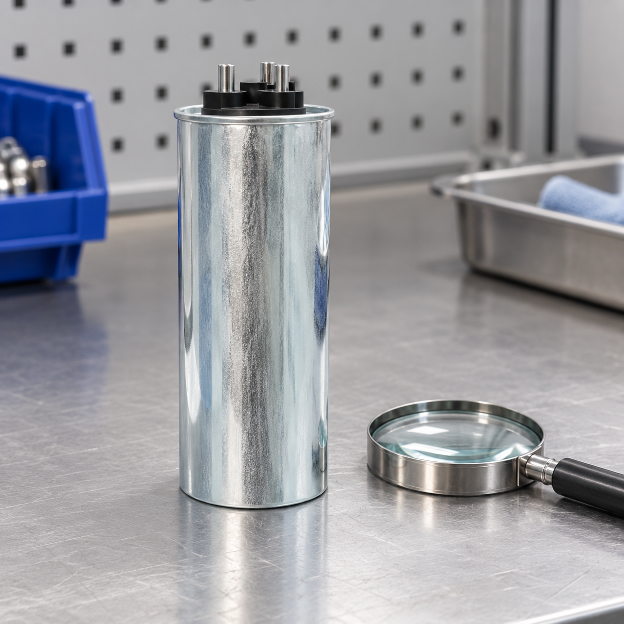
Dielectric damage and progressive capacitance loss
A self-healing capacitor can clear small local dielectric defects by removing a tiny conducting area around a fault. This does not make it immune to sustained overload or restore every cleared area. Many local events can progressively reduce useful electrode area. A unit may therefore produce less fundamental reactive power while its outer case still looks normal. Appearance is useful evidence, but it is not a capacitance test.
Compare an isolated measurement with the correct nameplate value, the original commissioning record and the manufacturer’s method. Identify whether the measurement represents one branch or a terminal pair in an internally connected three-phase unit. Parallel elements and discharge resistors can affect what a meter sees. A stable but low reading needs confirmation before assigning it to aging; a blown fuse or disconnected branch can imitate the same system-level symptom.
Overvoltage and harmonic stress
At a fixed sinusoidal frequency, capacitor current depends on capacitance and voltage. Harmonic components add current according to their own frequencies and amplitudes, so the fundamental current alone can understate electrical duty. The elementary capacitor relationships are explained in OpenStax’s AC capacitor discussion. A field decision still requires the actual waveform, product ratings and network study.
Measure capacitor-terminal voltage as well as the bus voltage. A series reactor changes the voltage across the capacitor; a bus reading cannot simply be substituted for that terminal value. Record individual phase currents and harmonic components when an approved operating test is possible. If damaged equipment must remain isolated, use existing recordings or a separately approved investigation; do not recreate a fault merely to obtain a graph.
A recent VFD installation, transformer change or bank expansion can alter resonance conditions. Check those changes before ordering identical replacement parts. The reactor purpose guide provides the broader branch-design context. Replacing a capacitor without checking its matching reactor can leave the original stress unchanged.
Heat, cooling and termination problems
Separate room temperature, enclosure inlet temperature, case temperature and terminal temperature in the report. They answer different questions. A hot room can affect every stage, while one poorly ventilated compartment may affect only a row of units. A concentrated hot spot at a connection points toward a different investigation from broadly elevated casing temperatures. Comparative thermal measurements should use consistent surface conditions and an appropriate method.
Dust, blocked vents, failed fans and nearby heat-producing reactors can reduce cooling. Look for evidence that the cabinet was changed after commissioning: filters added without airflow review, cable bundles blocking passages or equipment mounted in previously free space. Do not assume removing a cover is an acceptable permanent cooling solution. Restore the approved enclosure design and investigate the heat source and operating duty.
Switching and protection can imitate capacitor failure
A stage that never develops current may have an open fuse, damaged cable or switch that has failed to close. A controller output indicator only confirms a command. Compare the actual circuit state with the drawing. Repeatedly replacing a fuse with the same rating without understanding event timing loses valuable evidence and can expose replacement equipment to the same fault.
Distinguish failures during initial connection from failures after prolonged operation. The first directs attention toward switching duty and transient conditions; the second may involve sustained current, temperature or insulation deterioration. Both need complete coordination checks. An ordinary contactor and a capacitor-duty contactor are not interchangeable merely because their nominal current markings look similar.
Unexpected leading power factor at light load can come from a stage remaining connected rather than a damaged dielectric. Check signed reactive power, minimum-load behavior, controller settings and actual branch state. The bank maintenance checklist helps place these checks within a repeatable maintenance visit. Keep a component diagnosis distinct from a system control correction.
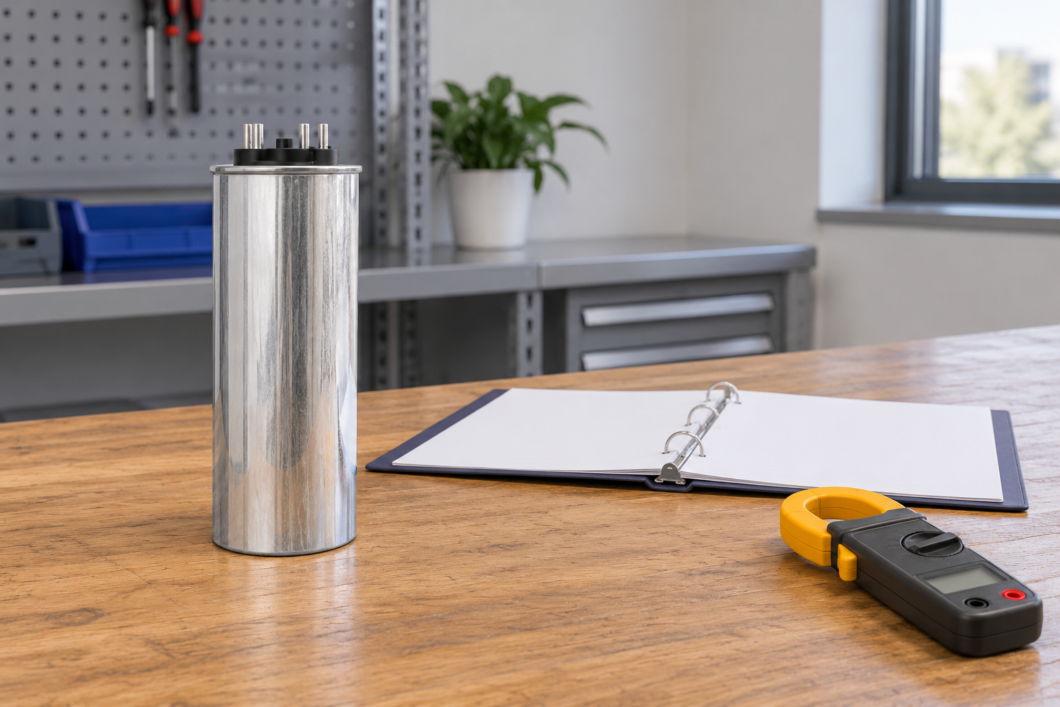
A practical investigation sequence
First preserve the event time, alarms, controller commands and available measurements. State which stage is affected and whether the symptom occurred during connection, steady running or disconnection. Document recent load and equipment changes. These observations often provide more useful direction than a single resistance reading taken later at a bench.
After the approved safe access procedure, inspect the unit, terminals, fuse, switch, discharge circuit and reactor against the drawings. Record what was found before cleaning or replacing parts. Perform only the tests authorized for the product and installation. A capacitance result, insulation result and protection test describe different functions; none should be relabelled as a universal pass certificate.
Then compare the stage with equivalent healthy stages under comparable conditions. Check whether ratings, operating hours and cooling arrangements really match before treating a difference as abnormal. Assemble the evidence into a cause statement with alternatives: confirmed failed component, likely stress source and any unresolved measurement. If the evidence cannot separate those possibilities, keep that uncertainty in the work order rather than ordering a speculative replacement.
Replacement and return-to-service decisions
An enquiry should include the original nameplate, internal connection, voltage and frequency, stage kvar, matching reactor data, dimensions, mounting, discharge arrangement and protection details. Include the measured harmonic environment and failure photographs where available. Do not substitute a different voltage rating or capacitance solely because it fits the same space. A branch is a coordinated assembly, and changes can affect current and tuning.
Specify the acceptance process before installation. It should cover correct identification, physical installation, connections, protection and discharge functions, approved operational measurements and controller response. Compare the new evidence with the baseline at relevant load states. The responsible engineer should state whether the original cause was removed, reduced or remains unresolved.
Set a follow-up trigger tied to the failure mechanism. A cooling repair needs evidence that temperatures remain acceptable during demanding operation. A switching problem needs a repeatable switching test and event review. A network change needs the appropriate harmonic or impedance assessment. A generic next-year inspection date does not replace those focused checks.
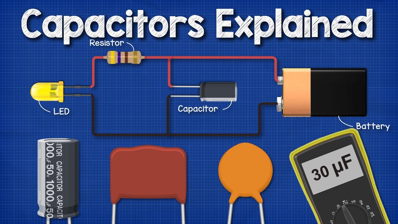
Educational video: capacitance and stored energy
The Engineering Mindset’s capacitor lesson explains charge storage, capacitor construction and measurement basics. Its small-component demonstrations support the concepts discussed here; they are not a procedure for discharging or testing an industrial bank. The complete investigation above can be used without the video.
Sık sorulan sorular
Does poor power factor prove a capacitor has failed?
No. An open fuse, disabled stage, failed switch, changed load or measurement error can also reduce the observed correction. Confirm stage state and branch measurements before blaming the capacitor.
Is a normal-looking case enough to return a unit to service?
No. Appearance cannot prove capacitance, insulation, discharge or operational suitability. Use the approved inspection and test criteria for that unit.
Can a replacement capacitor solve repeated fuse failures?
Only if the capacitor is the confirmed cause and the circuit conditions are suitable. Protection, switching, harmonics and the matching reactor may also require correction.
What should be retained in the failure report?
Keep the original event, rating, photographs, test method and results, cause assessment, replacement details, acceptance evidence and the next targeted follow-up.