


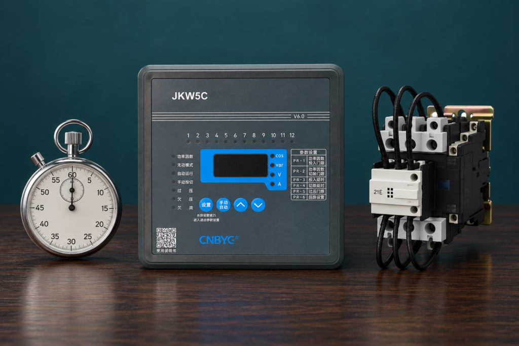
A capacitor switching delay setting should be chosen from the capacitor’s discharge and reconnection requirements, switching-device duty, controller algorithm and the plant’s load behavior. There is no universal delay suitable for every APFC panel. Distinguish the delay before a control decision from the minimum time a disconnected stage must remain off; they serve different purposes. A faster menu value does not make a mechanical contactor bank equivalent to a thyristor-switched system. Confirm the exact manuals and record the intended sequence before changing an operating panel.
This guide explains how to specify and verify timing without copying an arbitrary number from another installation. It complements automatic power-factor-controller settings and does not authorize rapid manual switching tests.
Different delays control different events
An APFC controller may provide several timing functions, and their names vary by model. One may wait after detecting reactive demand before issuing a stage command. Another may delay successive stage commands. A stage-specific lockout may prevent reconnecting the same capacitor before the approved discharge condition is met.
Minimum on time, minimum off time and response delay should not be assumed to be the same parameter. A controller may combine some functions, provide them separately or implement them through a particular algorithm. Read the exact definition and identify which transition each setting affects.
Record whether timing applies globally or independently to each stage. In a bank with several stages, a global interval between commands does not automatically guarantee that one particular stage has remained disconnected long enough. Stage-selection logic and individual reconnection protection need to be understood together.
Start with the capacitor’s discharge requirement
A disconnected capacitor can retain stored energy. A discharge device reduces that energy over time, but its presence does not mean the capacitor is immediately safe to touch or reconnect. The approved reconnection interval and safe-work procedure come from the actual equipment and installation requirements.
The California rule on draining stored capacitor charge addresses automatic discharge arrangements. This reference does not establish one reconnection time for every product. Obtain the manufacturer’s discharge specification, intended switching arrangement and any restrictions for the actual stage.
Do not shorten a controller lockout because a multimeter happened to show a low value during one isolated test. The design must account for the prescribed operating conditions, component behavior and measurement method. A maintenance test and a repeated operational reconnection requirement have different purposes.
Account for the switching device
A mechanical capacitor-duty contactor has electrical and mechanical duty limits. Frequent operations can increase wear, and capacitor switching has inrush characteristics that differ from ordinary resistive-load switching. Use the correct device selection and timing rather than treating every relay command as harmless.
A thyristor-switched arrangement can be designed for different response behavior, but its controller interface, switching condition, cooling and protection still need confirmation. Do not copy a fast-system setting into a contactor panel. A controller’s menu range is not evidence that all values are suitable for the installed hardware.
İnceleme capacitor-duty contactor selection when the bank uses mechanical switching. Confirm whether the quoted duty applies to the actual capacitor arrangement, harmonic environment and operating voltage. Timing selection cannot compensate for an incorrectly specified switching device.
Use a timing-function worksheet
| Timing function | Amaç | Seçim girişi |
|---|---|---|
| Demand-response delay | Avoid reacting immediately to short reactive-demand changes | Load profile and controller algorithm |
| Interval between stage commands | Allow a sequence to progress in a controlled way | Stage output, measurement settling and switching-device duty |
| Minimum stage off time | Prevent inappropriate reconnection of a recently disconnected capacitor | Manufacturer discharge and reconnection requirements |
| Minimum stage on time | Limit unnecessary rapid removal under the supported control logic | Operating profile and exact controller implementation |
| Alarm restart delay | Control return after a documented protective event | Fault cause, protection sequence and reset policy |
| Learning or test interval | Support stage-identification measurements | Manual prerequisites and stable test conditions |
The table identifies functions rather than universal values. The electricity authority’s APFC specification shows that programming, measurement and protection requirements should be defined together. Match the actual controller and bank documentation before assigning numbers.
Measure the load’s time behavior
Determine whether reactive demand changes over seconds, minutes or longer production cycles. Record motor starts, welding cycles, drive operation and periods of light load. The desired response should reflect meaningful demand changes rather than every brief disturbance.
A long delay can leave the plant undercompensated during a sustained load increase. A short delay can chase brief fluctuations and increase operations. The correct compromise depends on available stage sizes, switching technology and the evaluation method used by the utility or project.
Do not assess the result from one instantaneous display. Use a time-aligned log of reactive power, power factor, stage state and load condition. This reveals whether the bank corrects sustained demand, switches excessively or repeatedly overshoots into a leading condition.

Check stage size before using delay to suppress hunting
If the smallest available stage is larger than the reactive demand near the target, connecting it can overcompensate and removing it can leave a lagging condition. The controller may alternate between those states. Extending delay can reduce the operation rate but does not create a suitable intermediate kvar state.
Review the physical stage distribution, programmed ratios and any disabled stages. An originally small stage that no longer works can change useful resolution even though total installed nameplate capacity appears unchanged. Verify actual output before tuning timing.
For this distinction, see capacitor-bank step-size selection. If resolution is the root problem, correct the stage arrangement or control strategy using an approved design instead of relying on increasingly long delays to hide the symptom.
Make sure the measurement has time to settle
After a stage switches, the controller must evaluate the new operating condition using its measurement and filtering method. Rapid sequential commands can make interpretation difficult if load changes simultaneously or if the measured response has not settled according to the algorithm.
Confirm the controller’s supported procedure, including any averaging or learning requirements. A stage response that appears small may result from changing load, wrong CT location, incorrect scaling or a branch that delivers no output. Delaying longer does not resolve every one of those causes.
Use equivalent measurements at the regulation point and record command timestamps. Avoid forcing unnecessary switching while trying to diagnose the response. The goal is a controlled verification of the installed loop, not a stress test that ignores component limits.
Keep alarm reset and normal switching separate
An alarm restart sequence may include different timing from normal correction. Determine which stages remain blocked, whether automatic reconnection occurs and what conditions release the block. The timing must suit the protective event and the manufacturer’s intended recovery procedure.
Do not shorten restart delay to suppress repeated temperature or harmonic warnings. Investigate the cause first. If a fault persists, repeated reconnection can add switching stress without restoring acceptable operation. Record whether the controller’s alarm is a warning, a branch trip or a bank-level inhibit.
The California deenergized-equipment rule is a reference for stored-energy and isolation precautions during physical work. Menu adjustment and safe maintenance are separate tasks; a controller setting does not establish that disconnected equipment is safe to touch.
Program one change with a clear hypothesis
Save the original settings and their units before changing timing. State what the change is intended to achieve: for example, reducing response to brief load transients while retaining correction of sustained demand. Change one documented parameter at a time so the effect can be distinguished from other changes.
Confirm that the new value respects all component requirements. Observe the controller under the same representative load conditions used for the baseline. Record operation counts or event logs, residual reactive demand and any leading intervals. A quieter contactor panel is useful evidence, but it is not sufficient if correction has become ineffective.
If the controller has circular or optimized selection, identify whether the timing interacts with equivalent-stage rotation. Some stages may have different operating histories, so a bank-level command interval is not the whole story. The exact algorithm must be reviewed rather than inferred from the label.
When a faster compensation method should be evaluated
Some rapidly changing loads cannot be followed adequately by a conventionally switched capacitor bank within its safe duty. If the project requires a much faster response, evaluate suitable switching technology or dynamic reactive compensation through a proper engineering design.
Do not promise that an SVG or another device will meet every requirement without sizing, voltage, harmonic and integration data. Identify the actual reactive-demand profile and the performance objective. A technology change affects protection, installation, thermal conditions and control coordination as well as timing.
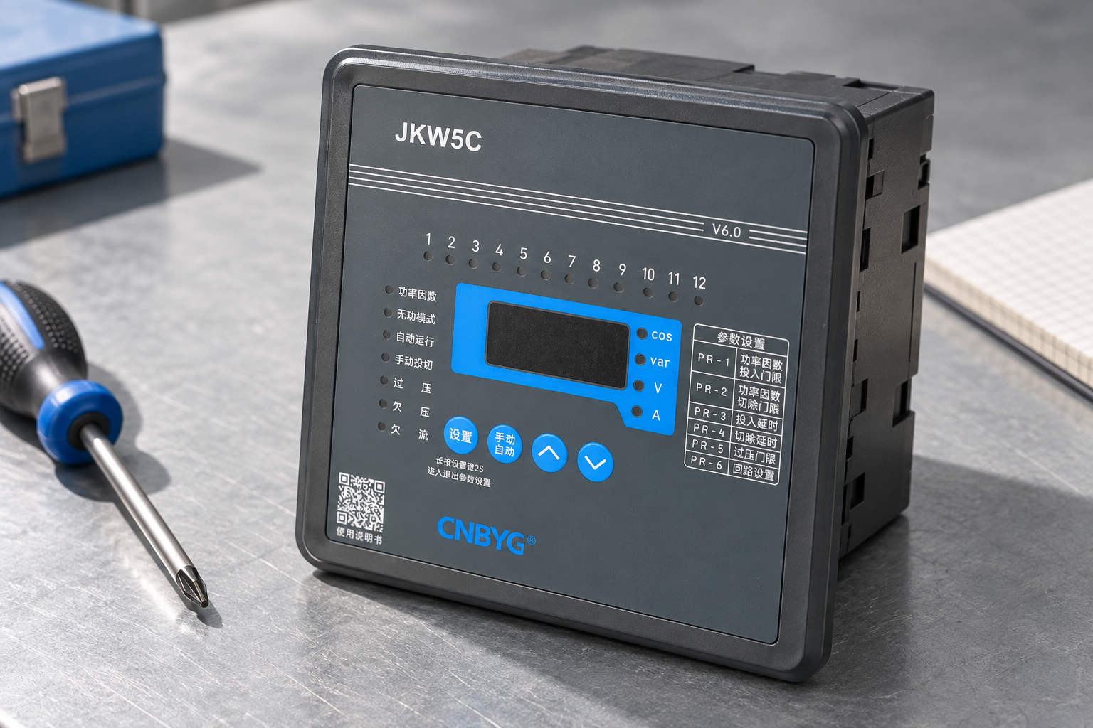
For CNBYG JKW controllers, submit the stage sizes, switching-device type, capacitor discharge requirements and load log. Request confirmation of the exact model’s timing functions and interface compatibility. The controller’s available menu settings alone do not define the panel’s safe response capability.

Verify and retain the result
After adjustment, confirm normal stage response, appropriate reconnection behavior and correct protection sequencing. Review a representative operating period rather than only a short commissioning moment. Include both production and light-load conditions where relevant.
Record the final parameter values, manual revision, component requirements, test conditions and measured effect. If a setting remains provisional, state the observation period and the criterion for accepting it. Preserve the earlier configuration so a future investigation can reconstruct why the timing changed.
The objective is controlled correction with acceptable equipment duty. It is not the fastest possible switching or the highest number of operations. A defensible timing record connects each value to a documented requirement and an observed improvement.
Further learning

Watch Lecture – 15 Power Factor by nptelhrd
The NPTEL power-factor lecture explains why reactive compensation is used. Apply the actual controller and capacitor manuals to timing, discharge and reconnection.
Sık sorulan sorular
Is there one correct switching delay for all APFC panels?
No. The value depends on capacitor reconnection requirements, switching-device duty, stage sizes, controller logic and load behavior. Use the exact equipment documentation.
Is response delay the same as capacitor discharge time?
Not necessarily. Response delay governs a control decision, while stage off-time protection may govern reconnection. Check which function each parameter actually implements.
Can a shorter delay make a contactor bank respond like a thyristor bank?
No. The hardware, interface, switching conditions and duty limits differ. A menu value cannot replace the appropriate switching-system design.
Will a longer delay cure stage hunting?
It may reduce the operation rate, but it does not fix oversized minimum stages, incorrect measurement or unsuitable sensitivity. Diagnose the cause and verify correction remains effective.